Table of Contents
Objective
This lesson will show you how to make the PiBot provide a video feed in a web page. First it will show you how to add the camera to the PiBot. Then it will show you how to program the PiBot to display a webpage with the video from the camera and allow you to drive it around.
Parts Required
The parts below are required to complete this lesson. Note that all parts are included in the OSOYOO kit that can be purchased on Amazon.
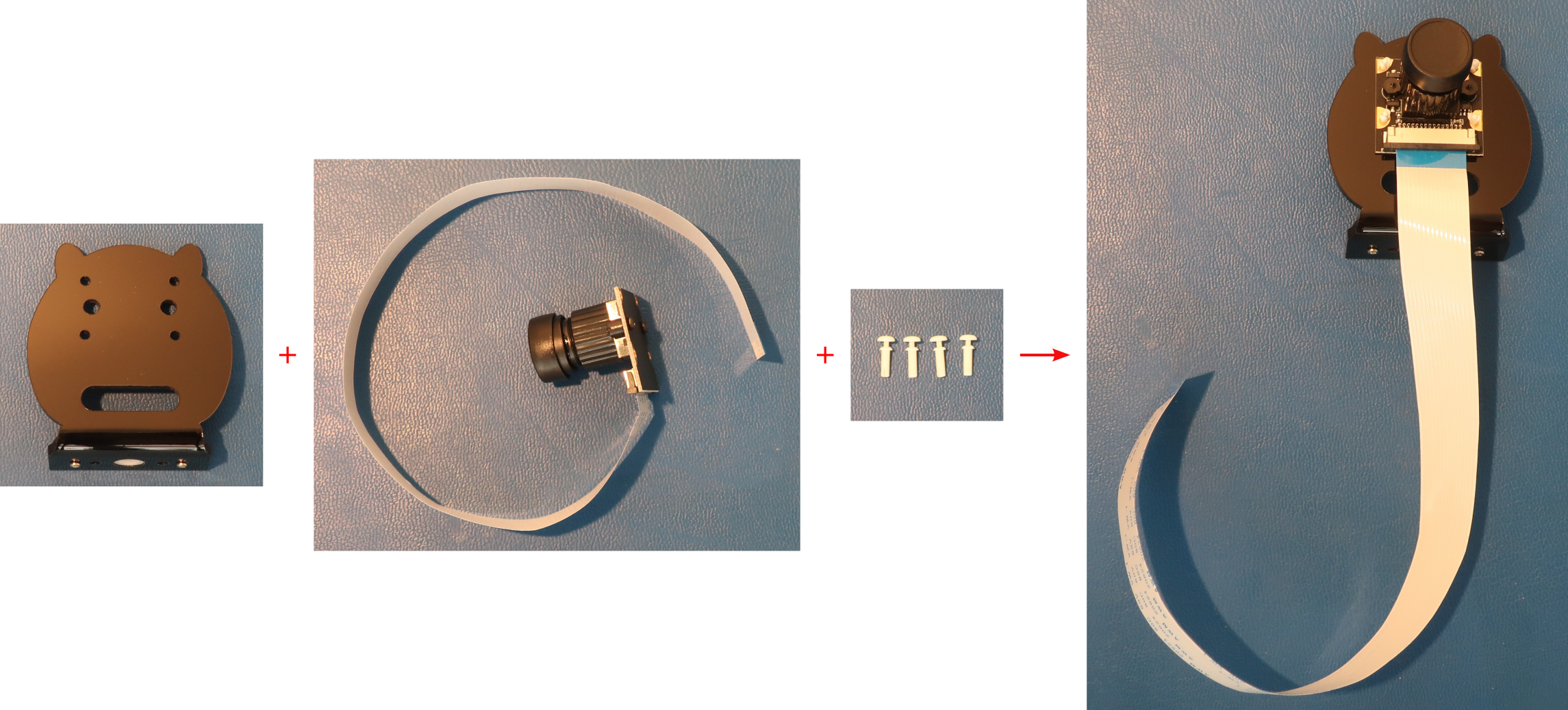
- CSI Camera and cable
- OSOYOO CSI Camera Holder
- Micro Servo Motor and Hardware
- Hardware
- M1.5x6mm Self Tapping Screws
- M2 Push Pin Rivets
- M2.2x8mm Self Tapping Screws
- M2x4mm Self Tapping Screws
Hardware Assembly
When handling any of the circuit boards make sure to wear your ESD wrist strap and have it connected to an earth ground point
When installing items with multiple screws or nuts, leave them loose until all are installed and then tighten to ensure that you can get them all inserted
- If starting from Lesson 2 perform the following step, otherwise skip to step 2
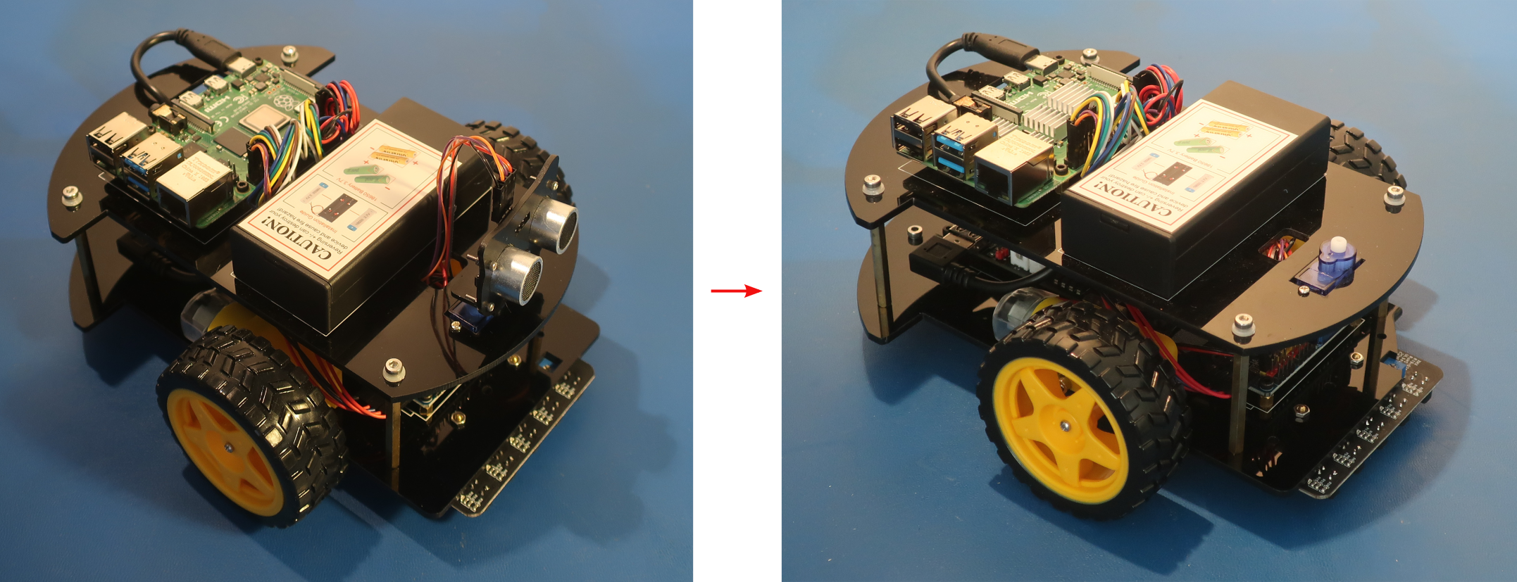
- Install the Micro Servo Motor on the top chassis with 2pcs M2.2x8mm self tapping screws from the hardware kit as shown below
Install the micro servo motor from the bottom of the top chassis plate. The M2.2x8mm screws should slide through the holes in the top chassis plate and screw into the holes on the micro servo motor.
- If starting from Lesson 3 perform the following step, otherwise skip to step 3
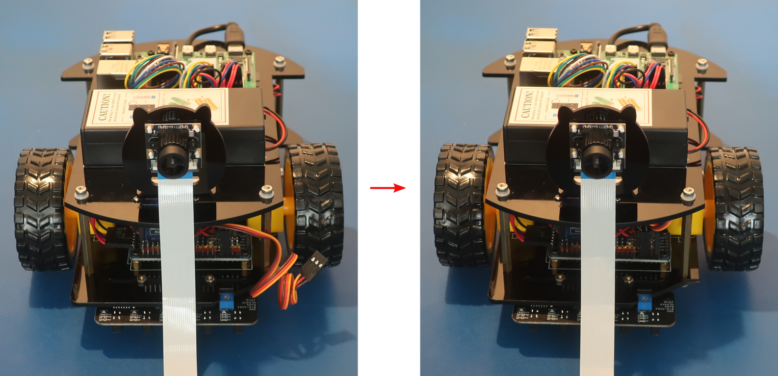
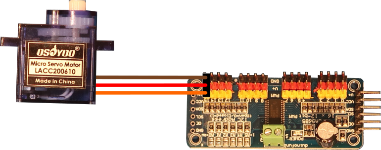
- Connect the Micro Servo Motor to the PCA9685 compatible board as shown below
If you started with the Lesson 3 PiBot then skip this step
Create loops in the wires by wrapping them around your finger to keep the wiring neat
Channel 15 on the PCA9685 module is all the way on the right side when looking at the PiBot from the front
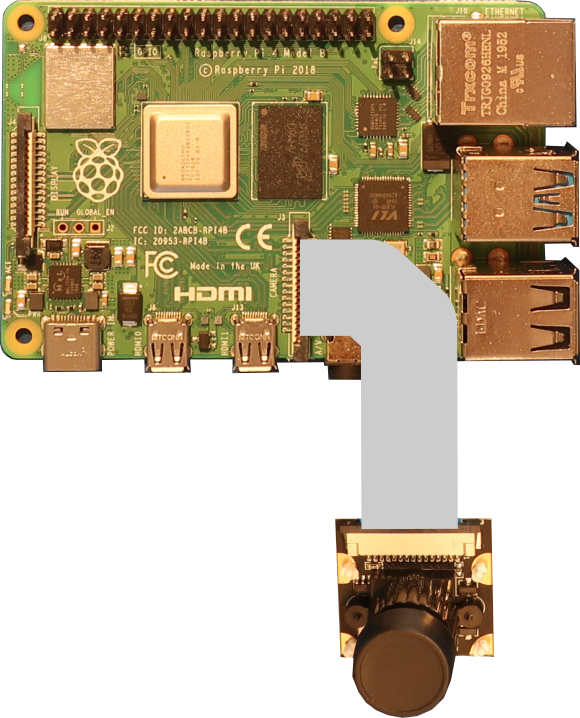
Micro Servo Motor PCA9685 Module GND (Brown) GND15 5V (Red) V+15 SIG (Orange) PWM15 - Connect the CSI Camera to the Raspberry Pi board as shown below
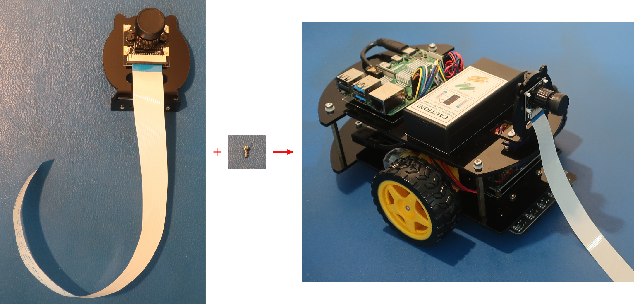
Feed the CSI ribbon cable through the slot in the CSI camera holder to bring it back to the Raspberry Pi board
Make sure to slide the black latch on the Raspberry Pi CSI connector up before inserting the CSI ribbon cable. Push the black latch down until it clicks after inserting the CSI ribbon cable
CSI Camera Raspberry Pi Board J1 CAMERA - Turn the PiBot on and place it so that it can drive around
Remove the cover from the lens of the CSI camera before turning the PiBot on
Software
Select the appropriate link below for instructions to setup the software on the PiBot and an exploration of how it works.
Electrical Description
The CSI camera has a lens that focuses the light of a scene onto a CMOS image sensor that converts the light into a digital signal that you can view on your screen. The CMOS image sensor has millions of small light sensors called pixels that each measure how many photons of light are hitting it. The CMOS image sensor reads the pixels line-by-line to determine how many photons each has measured, and sends that information back to the Raspberry Pi to display the image.
Since each pixel can only measure how many photons hit it, to get the different colors that we see there are red, green, and blue filters in front of the pixels so that each one measures the number of red, green, or blue photons that hit it. Because our eyes are more sensitive to green light, there are actually twice as many green pixels on the CMOS image sensor as there are red or blue pixels. The Raspberry Pi combines the pixel information into a single Red-Green-Blue (RGB) value that is displayed on your screen.


