Table of Contents
Objective
This lesson will show you how to make the PiBot avoid obstacles in front of it. First it will show you how to add the ultrasonic distance sensor to the PiBot. Then it will show you how to program the PiBot to avoid obstacles that are in front of it. Finally it will describe how the electronics let the PiBot “see” the obstacles and turn to avoid them.
Parts Required
The parts below are required to complete this lesson. Note that all parts except the styrofoam blocks and optional hardware are included in the OSOYOO kit that can be purchased on Amazon.
- HC-SR04 Ultrasonic Distance Sensor
- OSOYOO Ultrasonic Distance Sensor Holder
- Micro Servo Motor and Hardware
- 20cm Female to Female Jumper Wires
- Styrofoam Blocks that are at least 5in tall and 2in thick
- Hardware
- M1.5x8mm Screws
- M1.5 Hex Hex Nuts
- M2.2x8mm Self Tapping Screws
- M2x4mm Self Tapping Screws
- Optional Hardware
- M1.4x8mm Hex Cap Screws
- M1.4 Hex Hex Nuts
- M1.6x8mm Hex Cap Screws
- M1.6 Hex Hex Nuts
Hardware Assembly
When handling any of the circuit boards make sure to wear your ESD wrist strap and have it connected to an earth ground point
When installing items with multiple screws or nuts, leave them loose until all are installed and then tighten to ensure that you can get them all inserted
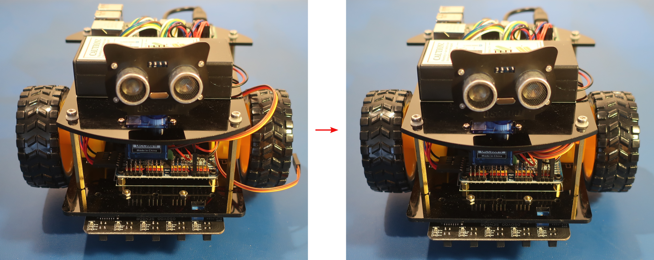
- Install the Micro Servo Motor on the top chassis with 2pcs M2.2x8mm self tapping screws from the hardware kit as shown below
Install the micro servo motor from the bottom of the top chassis plate. The M2.2x8mm screws should slide through the holes in the top chassis plate and screw into the holes on the micro servo motor.
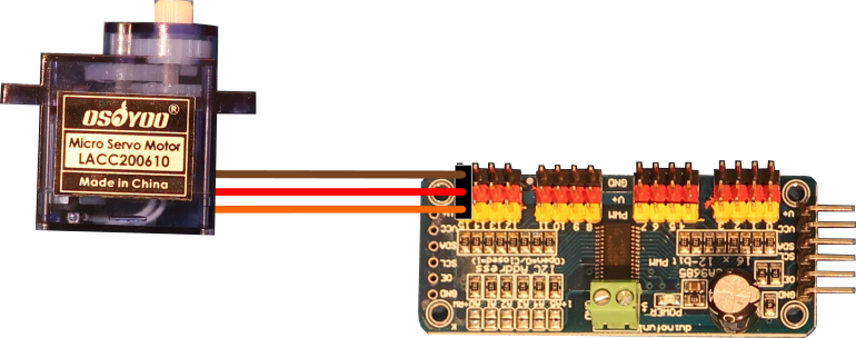
- Connect the Micro Servo Motor to the PCA9685 compatible board as shown below
Create loops in the wires by wrapping them around your finger to keep the wiring neat
Channel 15 on the PCA9685 module is all the way on the right side when looking at the PiBot from the front
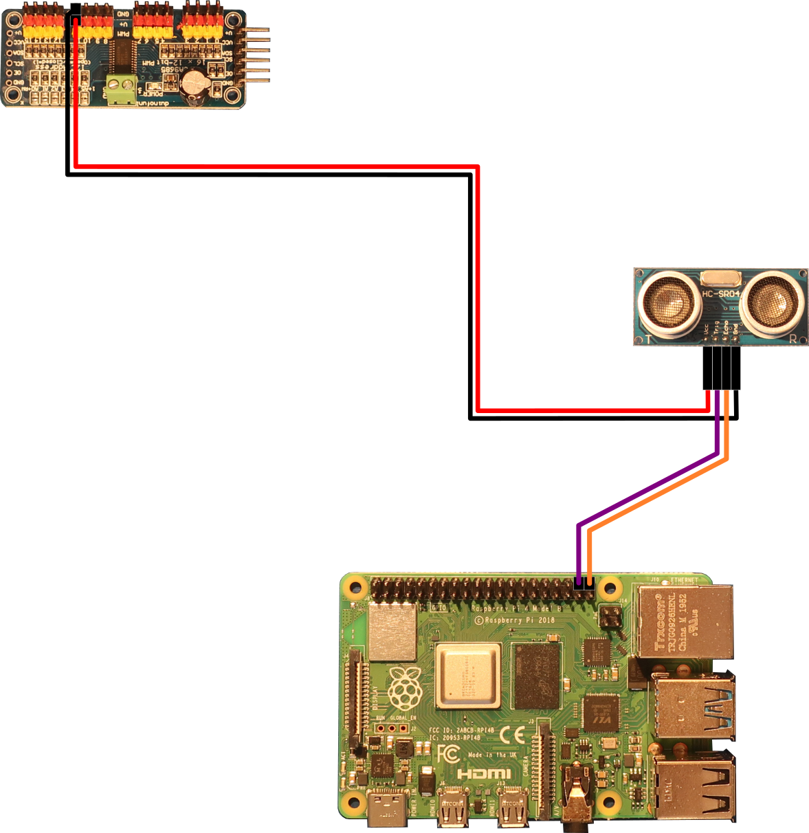
Micro Servo Motor PCA9685 Module GND (Brown) GND15 5V (Red) V+15 SIG (Orange) PWM15 - Connect the Ultrasonic Distance Sensor to the PCA9685 compatible board and Raspberry Pi board as shown below
Pull the wires one at a time to separate them from the wire bundle
Twist the pairs of wires that go to the same board together and create loops in the wires by wrapping them around your finger to keep the wiring neat
Feed the wires through the small rectangle hole in the top chassis to get them to the PCA9685 compatible board. To keep the wires to the Raspberry Pi neat, feed them down through the small rectangle hole in the top chassis and back up the large rectangle hole in the top chassis to get them to the Raspberry Pi board.
Use a pair of needle-nose pliers or tweezers to help feed the new wires past the other wires between the top and bottom chassis plates
Leave some slack in the wires near the Ultrasonic Distance Sensor so that the servo can turn it
Ultrasonic Distance Sensor PCA9685 Module Raspberry Pi Board VCC V+11 — Trig — Pin 38 (GPIO 20) Echo — Pin 40 (GPIO 21) GND GND11 — - Setup some styrofoam blocks to create obstacles for the PiBot
Use some walls of the room to create a box with the styrofoam blocks that the PiBot can drive around in
- Turn the PiBot on and place it so that some of the styrofoam blocks are in front of it
Software
Select the appropriate link below for instructions to setup the software on the PiBot and an exploration of how it works.
Electrical Description
The HC-SR04 Ultrasonic distance sensor has 2 ultrasonic transducers. One transducer acts like a speaker to send out ultrasonic pulses and the other one acts like a microphone to receive the pulses that bounce back. The ultrasonic pulses are sounds that are above the frequencies that humans can hear, so to us it is silent. Humans cannot hear sounds above $20kHz$ and the HC-SR04 sends out ultrasonic pulses at $40kHz$.
When the $10\mu s$ trigger pulse is given to the HC-SR04, it sends out 8 pulses of $40kHz$ sound using the speaker transducer. When it finishes sending out the pulses, it sets the echo pin high and waits to hear any reflections that might bounce back from something in front of it. When it receives an echo, it sets the echo pin low, and if no echo is received it has an internal timer that will set the echo pin low after $38ms$.
The time that the echo pin is high can be used to determine how far from the transducer an object is located. Since the distance to the object is just the speed of the sound multiplied by the time it takes to get there we can use that formula to calculate the distance to the object. This is the formula that is provided in the datasheet and below in equation \ref{eqn1}. The speed of sound in the air is generally a constant of $343m/s$. When you multiply the time that the echo pin is high with that constant speed, you get the distance that the sound pulses traveled. Since the sound had to travel out to the object and then back to the ultrasonic distance sensor, the distance from the sensor to the object is $1/2$ the total distance calculated. To see a graphical representation of how the HC-SR04 works check out this site.
\begin{equation}Distance (m) = {Time (s) \times 343 (m/s) \over 2} \label{eqn1}\end{equation}
The trigger and echo pins are connected to the Raspberry Pi GPIO so that the Raspberry Pi can control when a measurement is started and detect the time that the echo pin is high.
The PiBot uses the Micro Servo Motor to turn the Ultrasonic Distance Sensor so that it can detect if any objects are to the left or right of it in addition to straight in front of it. The micro servo motor uses a PWM signal that tells it what angle to turn to. This is similar to how PWM works to control the motors as described in Lesson 1. The micro servo motor can rotate up to $180^{\circ}$ and the angle is determined by the high time of the PWM signal.
The micro servo motor uses high times between $1ms$ and $2ms$ to represent the angles between $0^{\circ}$ and $180^{\circ}$ where $1ms$ is $0^{\circ}$ and $2ms$ is $180^{\circ}$. The PWM signal generates a high pulse based on the value passed to the set_pwm function on the Raspberry Pi. Each count of that value is equivalent to $4.069\mu s$ when the frequency is set to $60Hz$ as shown in equation \ref{eqn2} below. This means that each count is equal to $0.732^{\circ}$ of rotation on the servo as can be seen from equation \ref{eqn3} below.
\begin{equation} \begin{split} Count (s/cnt)& = {1/Frequency(Hz) \over MaxCount(cnt)}\\ & = {1/60(Hz) \over 4096(cnt)}\\ & = 4.069(\mu s/cnt) \end{split} \label{eqn2} \end{equation}
\begin{equation} \begin{split} Angle (^{\circ}/cnt)& = {MaxDegrees (^{\circ}) - MinDegrees (^{\circ}) \over MaxTime (s) - MinTime (s)} \times Count (s/cnt)\\ & = {180 (^{\circ}) - 0 (^{\circ}) \over 2 (ms) - 1 (ms)} \times 4.069 (\mu s/cnt)\\ & = 0.7324 (^{\circ}/cnt) \end{split} \label{eqn3} \end{equation}


