User Tools

Site Tools


mbotneo:lesson5

Objective

This lesson will show you how to program the mBot Neo to recognize colors while following a line. It will then show you how test your program on the mBot Neo.

Parts Required

The parts below are required to complete this lesson. Note that all parts are included in the mBot Neo kit that can be purchased on Amazon.

  1. Assembled mBot Neo from Lesson 1
  2. USB Cable
  3. Line following paper

Software Programming

  1. Connect the USB cable to the CyberPi on the mBot Neo and plug the cable into your computer

    This will charge up your mBot Neo while you create the program

  2. Open the mBlock app on your computer

    You can download the mBlock app from mBlock Download if it isn't already installed

    Open mBlock app

  3. Click on the Extension button

    Add new extension

  4. Click the Add button under the mBot2 shield

    Select mBot2 extension

  5. Click on the Extension button

    Add new extension

  6. Click the Add button under the Quad RGB Sensor

    Select quad RGB sensor extension

  7. Click the Upload button under the Mode Switch section

    This allows you to write your program without having the mBot Neo connected to your computer

    Select Upload mode

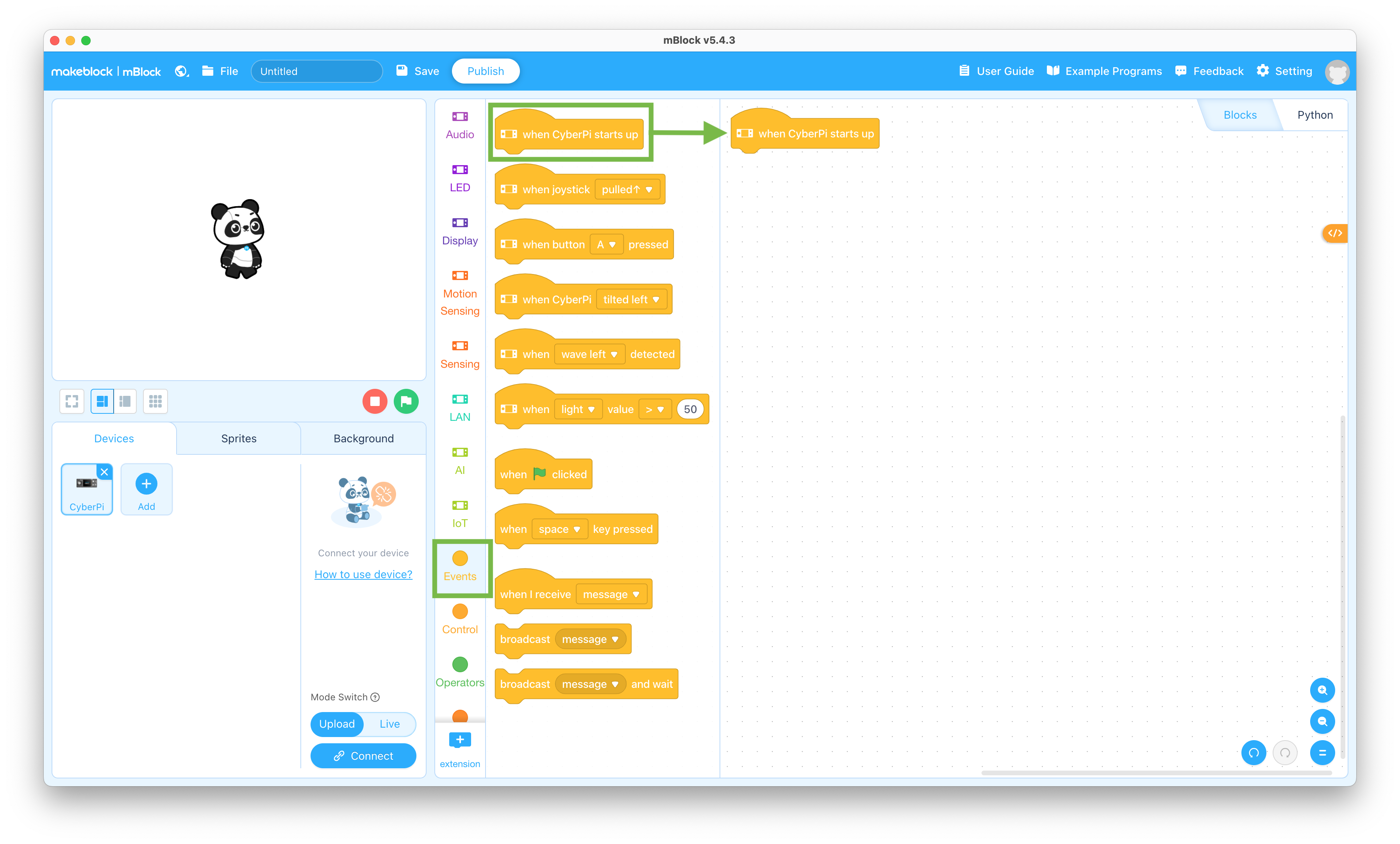
  8. Click the Events selector and drag the “when CyberPi starts up” block to the coding pane

    Startup block

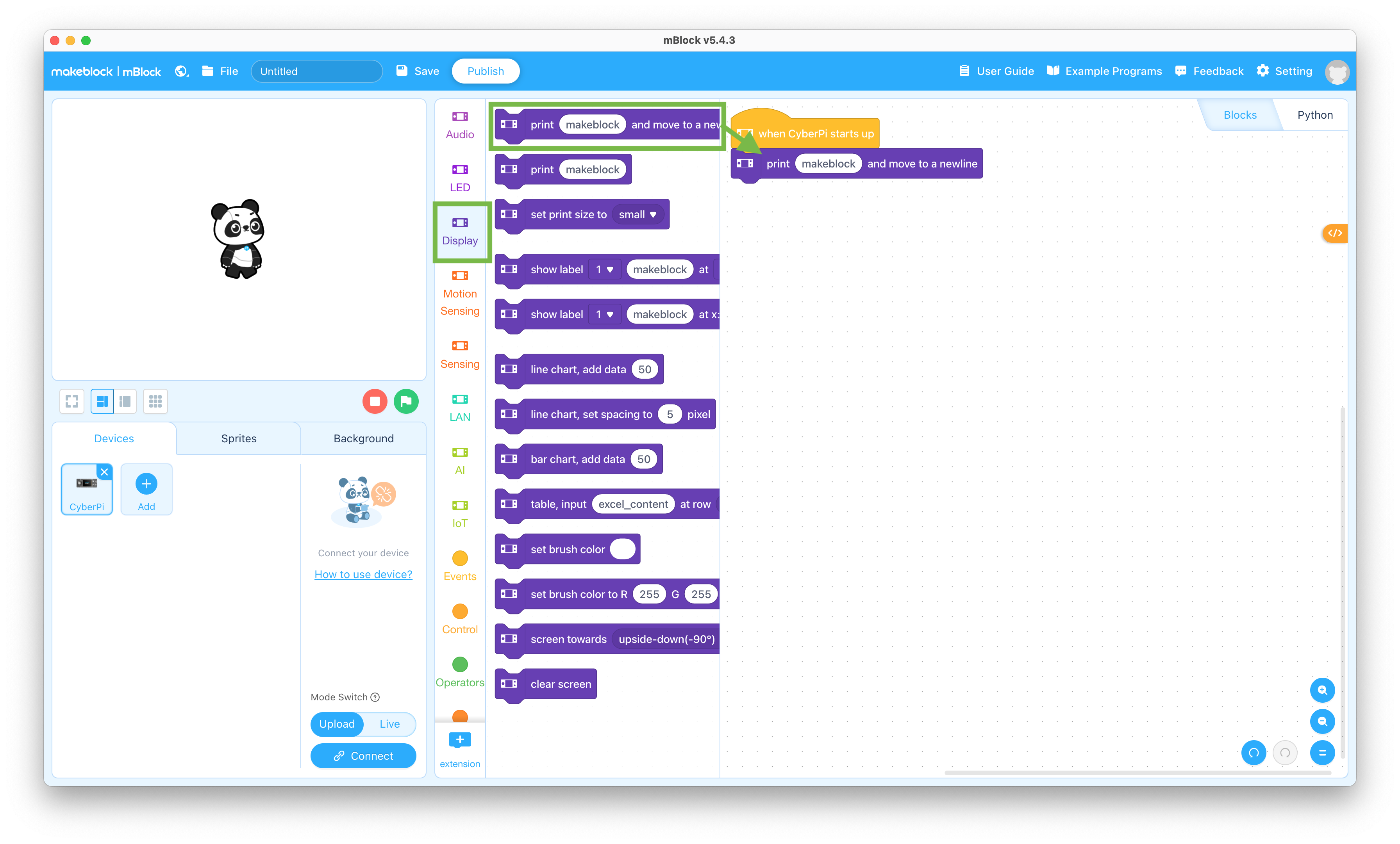
  9. Click the Display selector and drag the “print makeblock and move to a newline” block to the coding pane and snap it to the bottom of the stack

    Display block

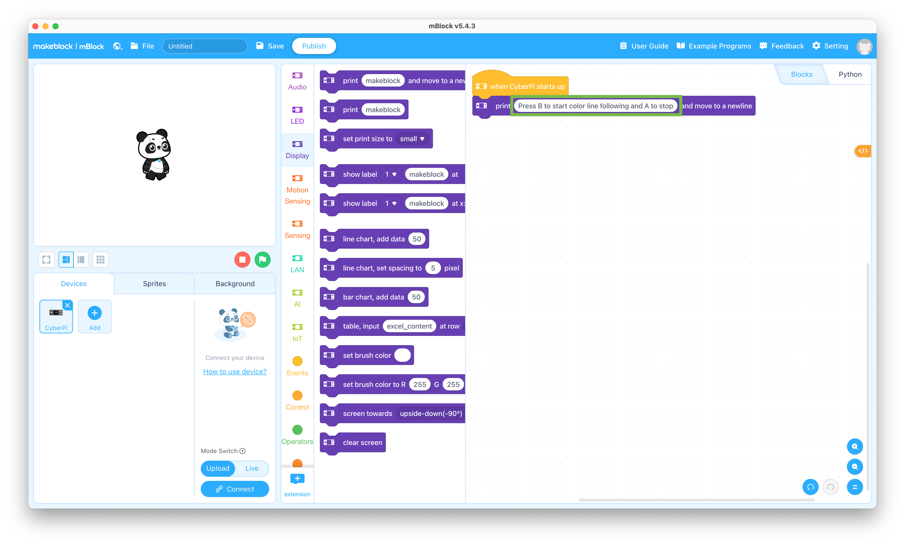
  10. Change the “makeblock” to “Press B to start color line following and A to stop” in the “print makeblock and move to a newline” block

    Set display message

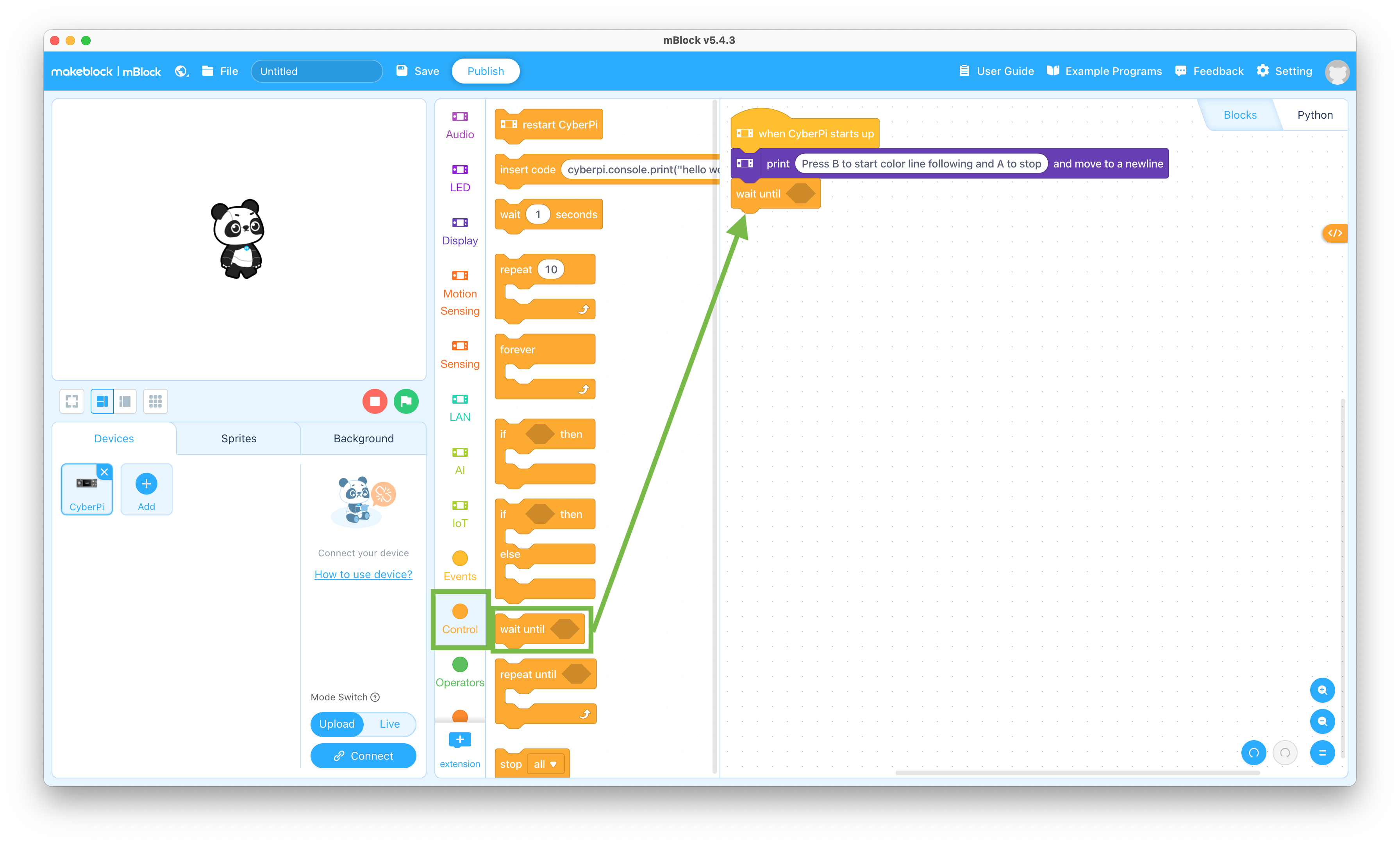
  11. Click the Control selector and drag the “wait until < >” block to the coding pane and snap it to the bottom of the stack

    Wait until block

  12. Click the Sensing selector and drag the “button A pressed?” block to the coding pane and snap it into the “wait until < >” block

    This allows you to control when the mBot Neo starts running the color line following after you power it on

    Button A pressed block

  13. Change the “A” to “B” in the “when button A pressed” block

    Set B button

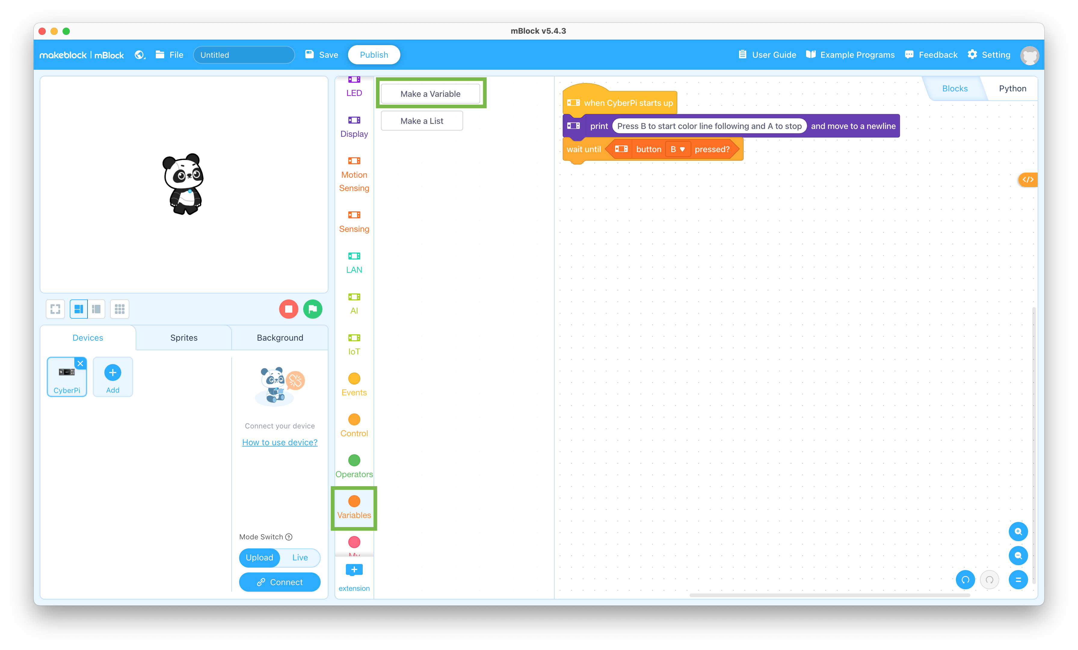
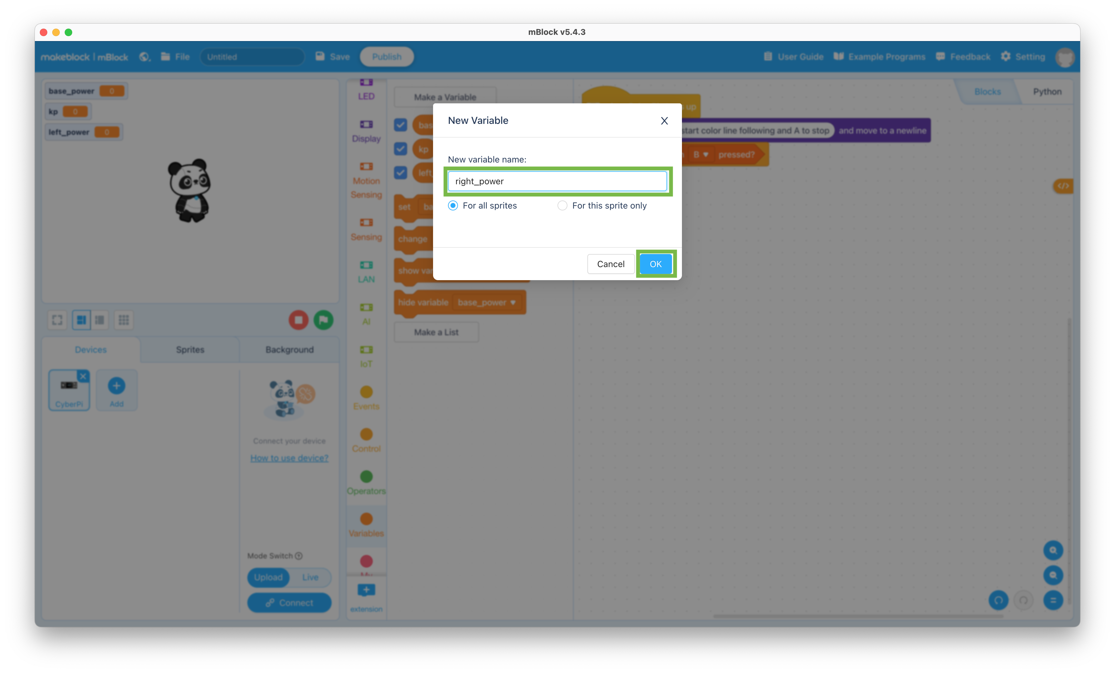
  14. Click the Variables selector and click the Make a Variable button to create the following variables for all sprites

    This will allow your program to store information that it needs and change it as it runs

    Create Variables

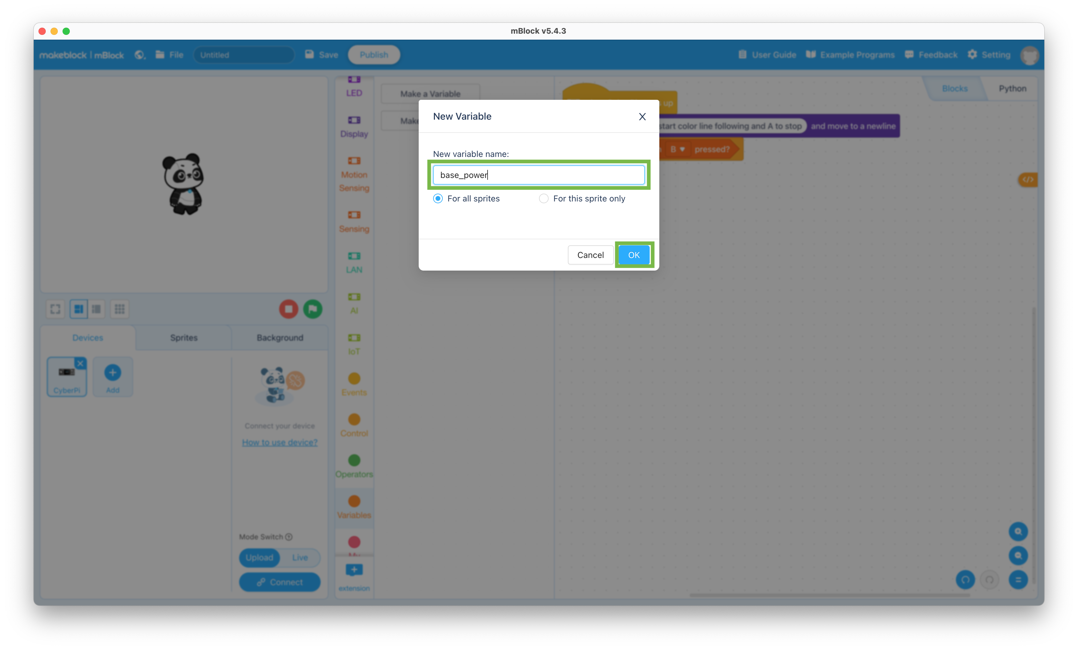
    1. base_power

      Create base_power variable

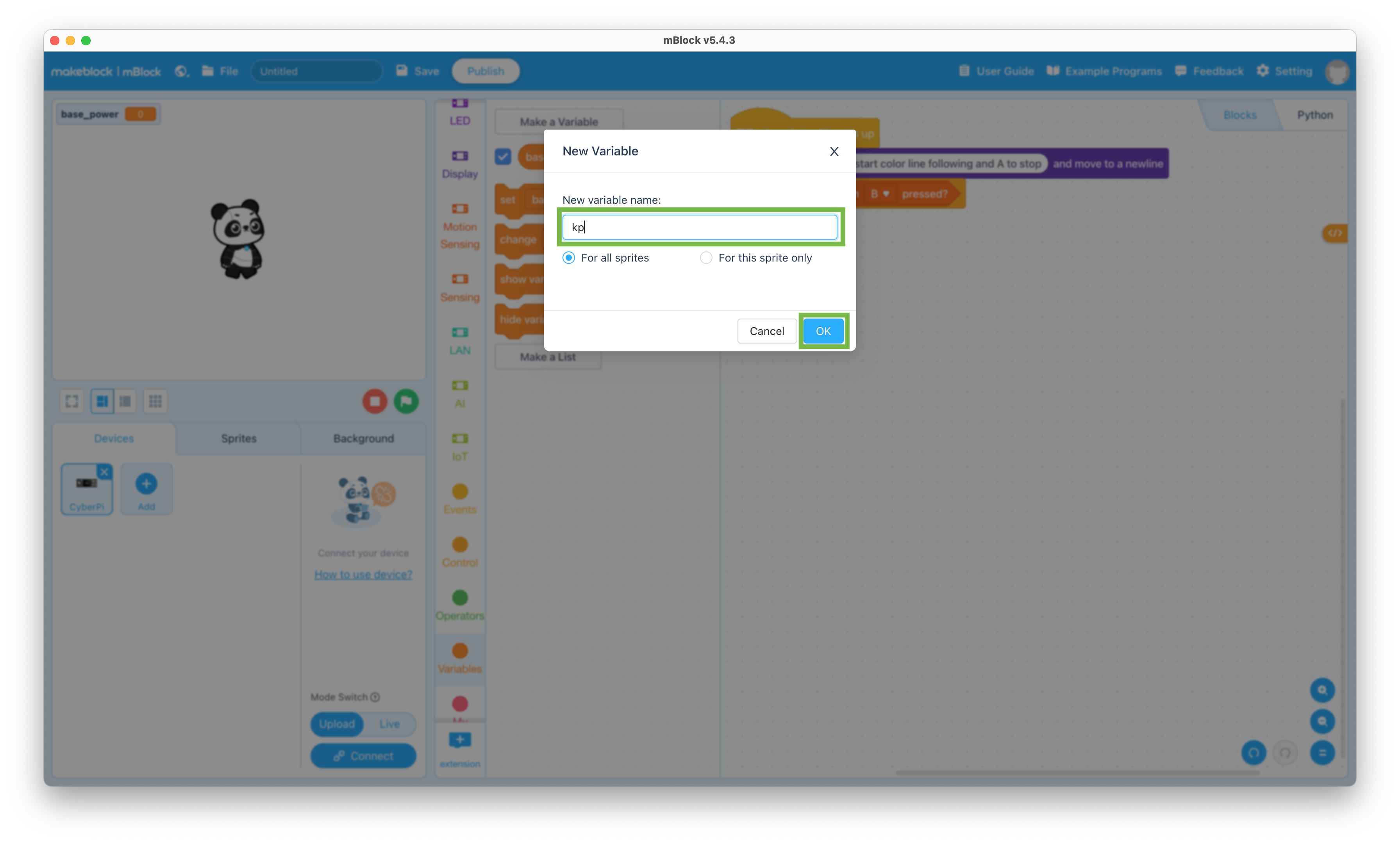
    2. kp

      Create kp variable

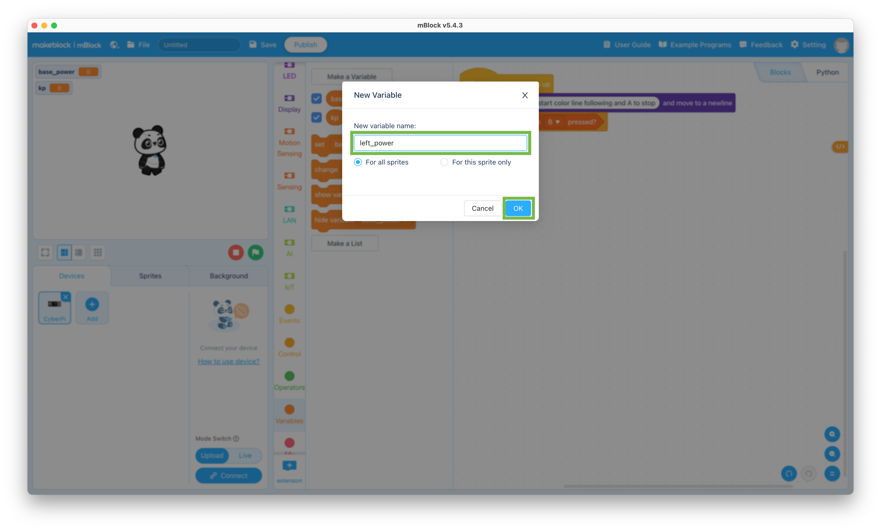
    3. left_power

      Create left_power variable

    4. right_power

      Create right_power variable

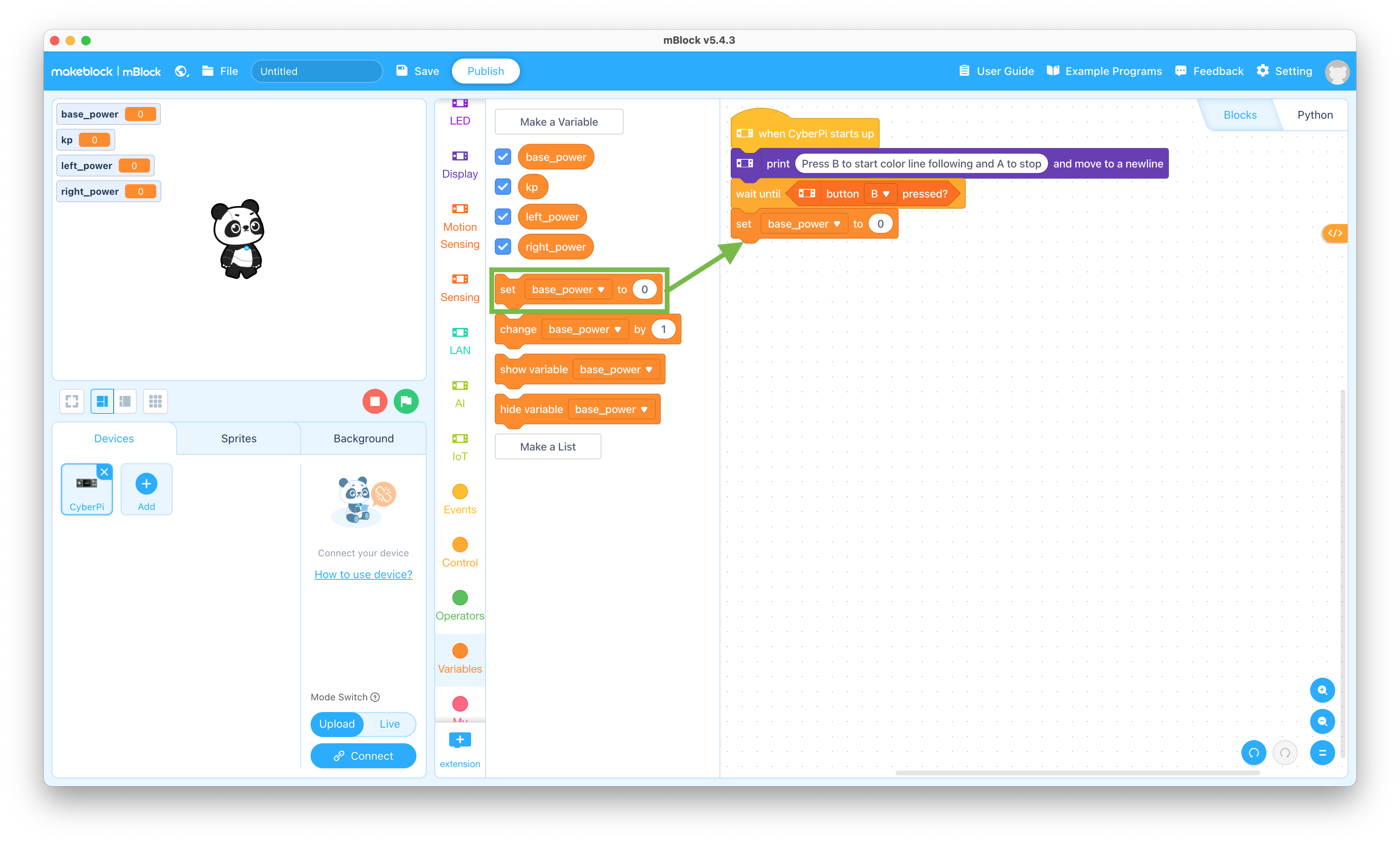
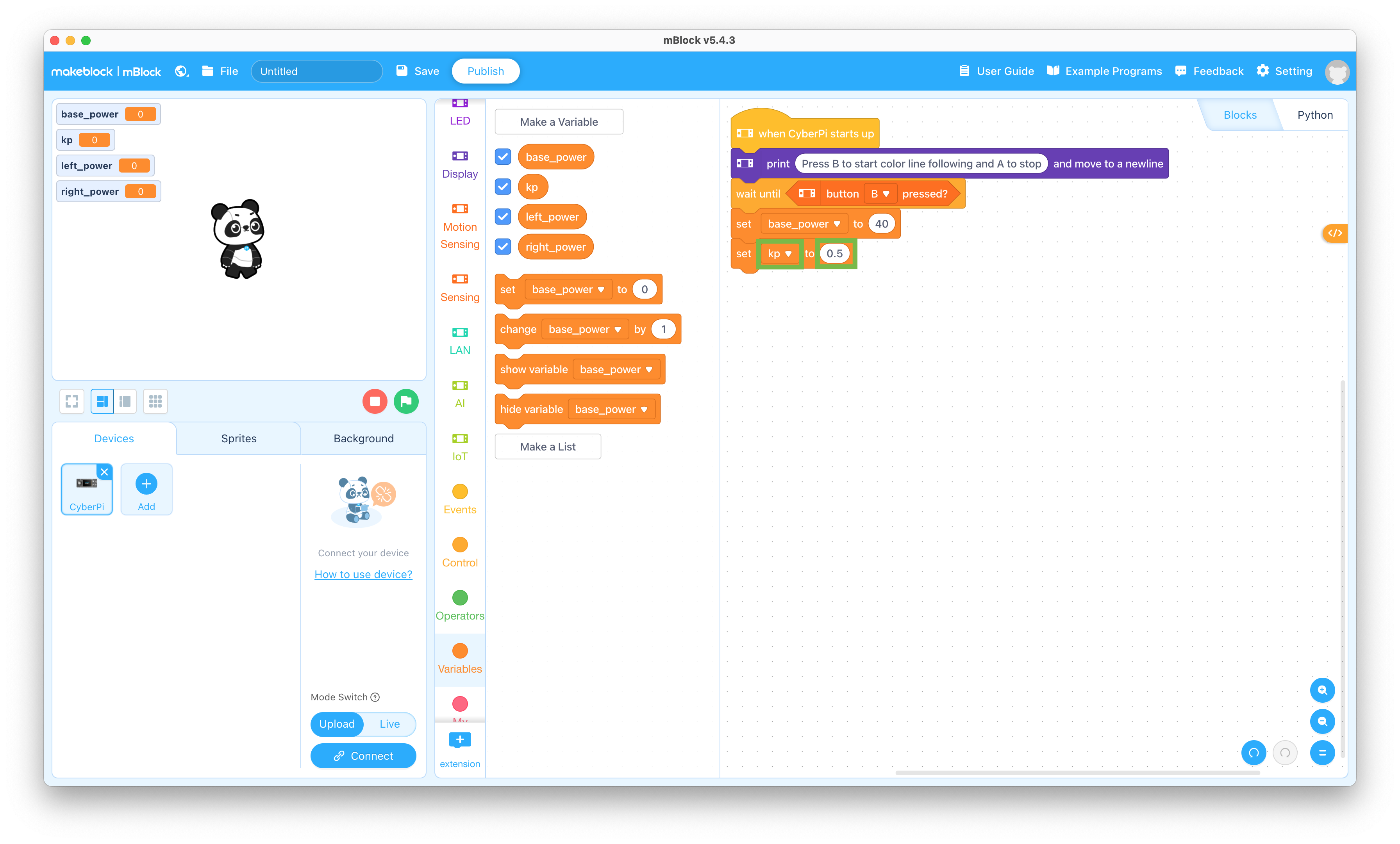
  15. Drag the “set base_power to 0” block to the coding pane and snap it to the bottom of the stack

    Set variable block

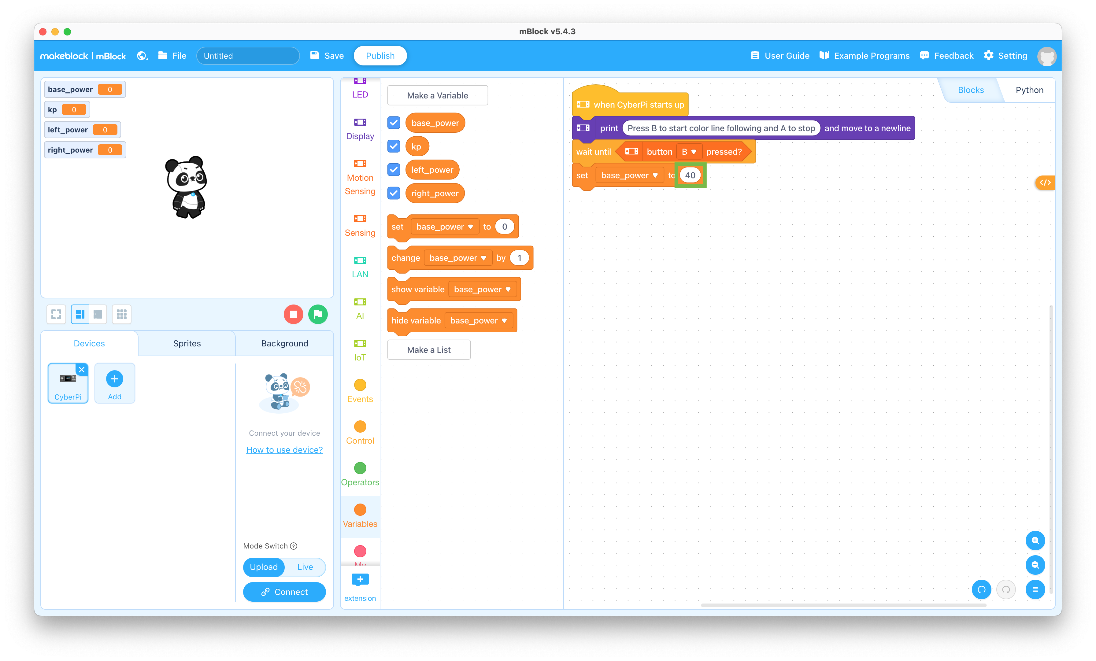
  16. Change the “0” to “40” in the “set base_power to 0” block

    Set base_power value

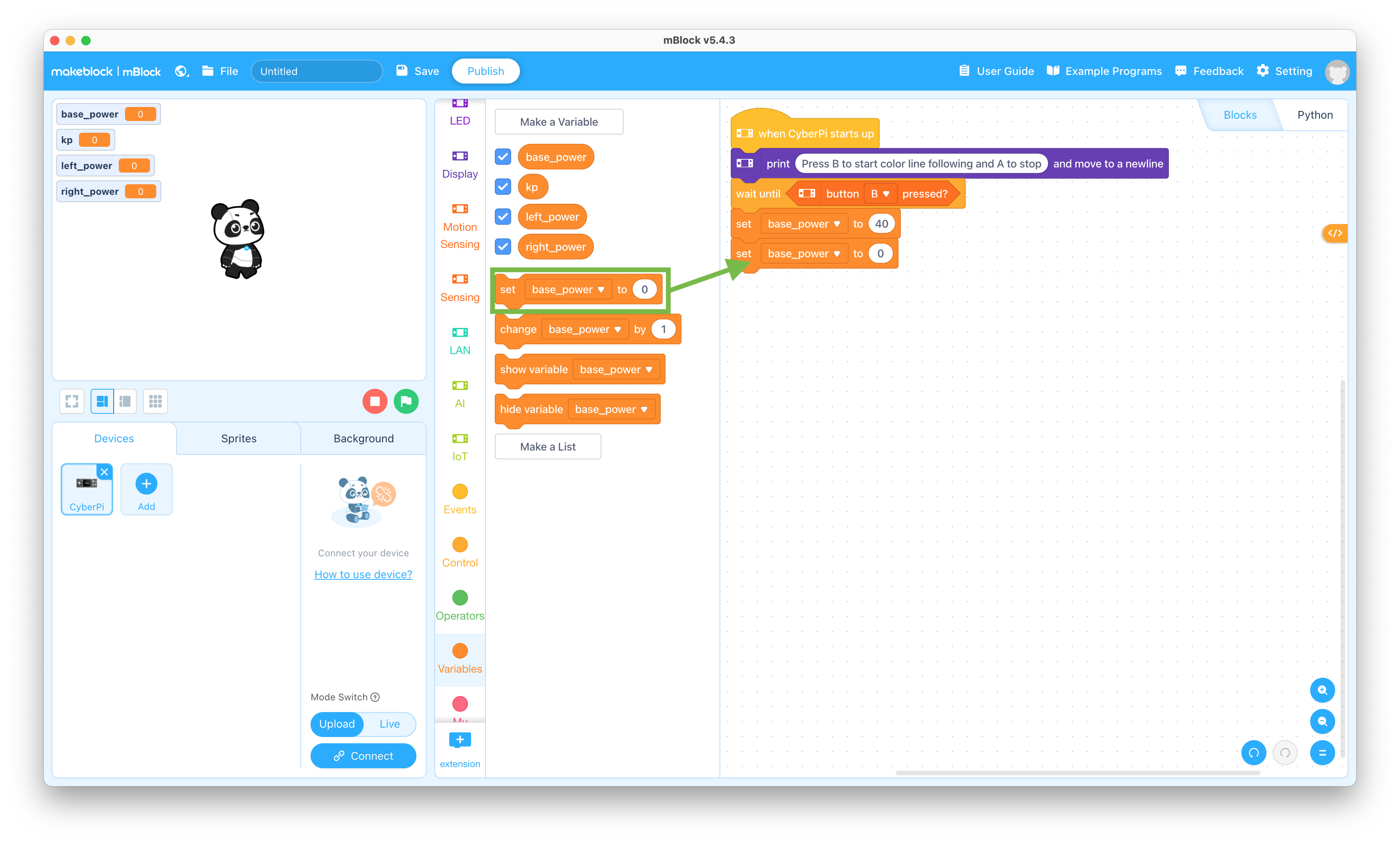
  17. Drag the “set base_power to 0” block to the coding pane and snap it to the bottom of the stack

    Set variable block

  18. Change the “base_power” to “kp” and the “0” to “0.5” in the “set base_power to 0” block

    Set kp value

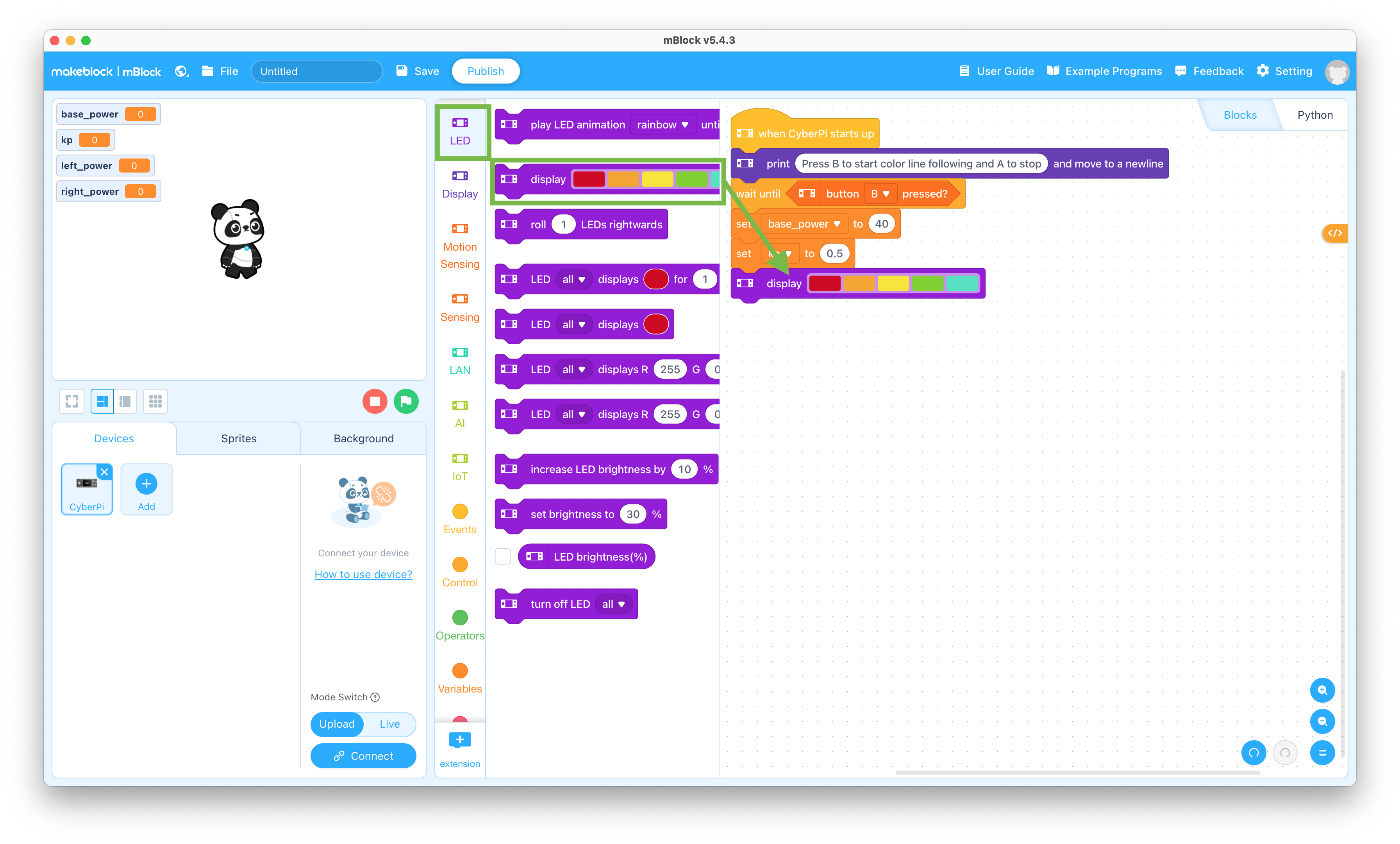
  19. Click the LED selector and drag the “display” block to the coding pane and snap it to the bottom of the stack

    This will allow your mBot Neo to display colors on its LEDs

    LED block

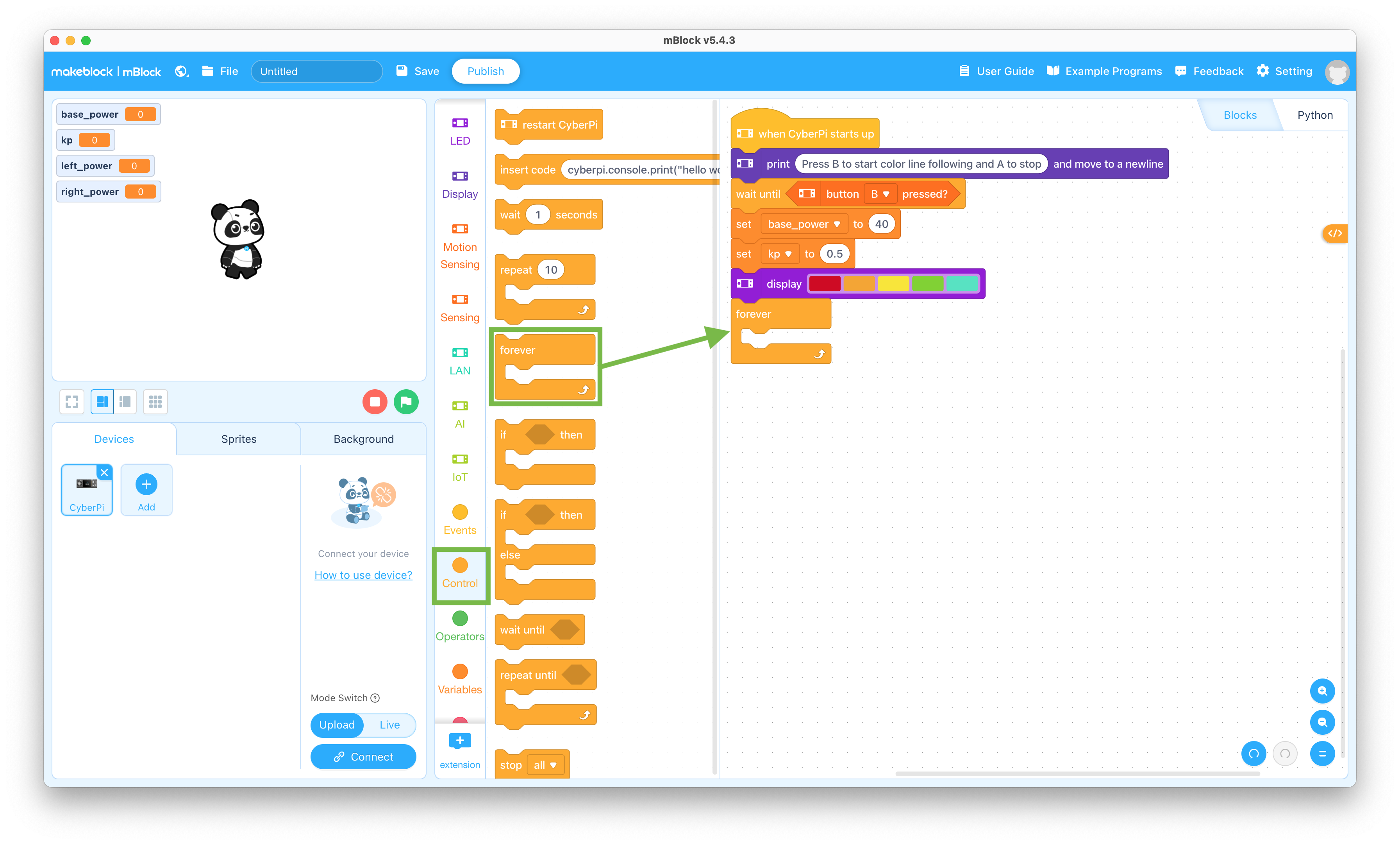
  20. Click the Control selector and drag the “forever” block to the coding pane and snap it to the bottom of the stack

    This will allow your program to keep running until you press the A button on the CyberPi

    Forever block

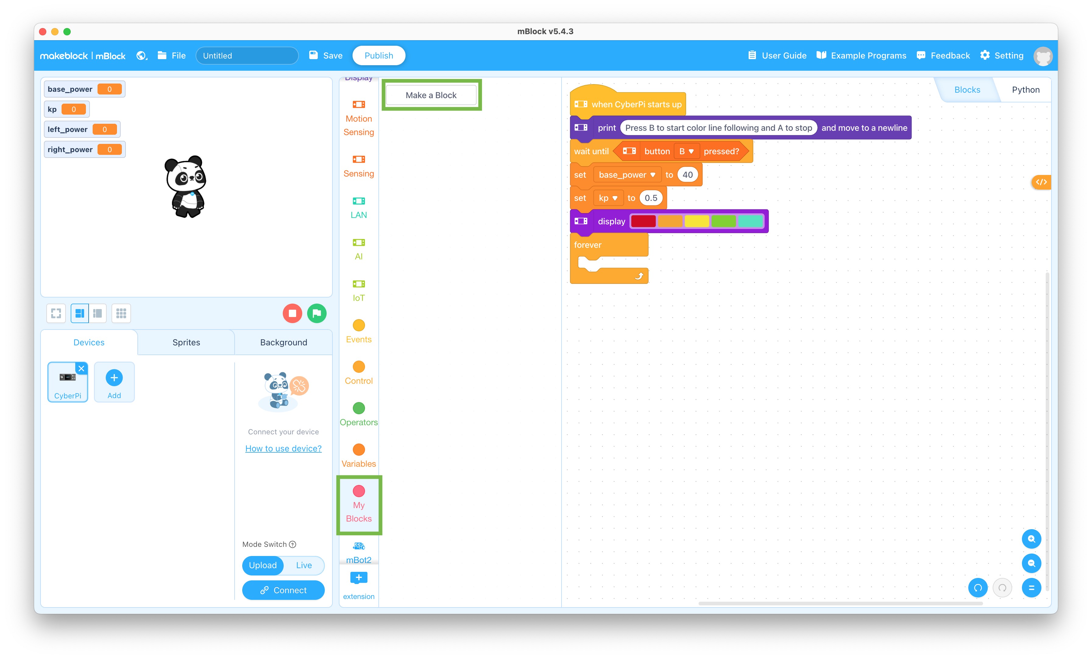
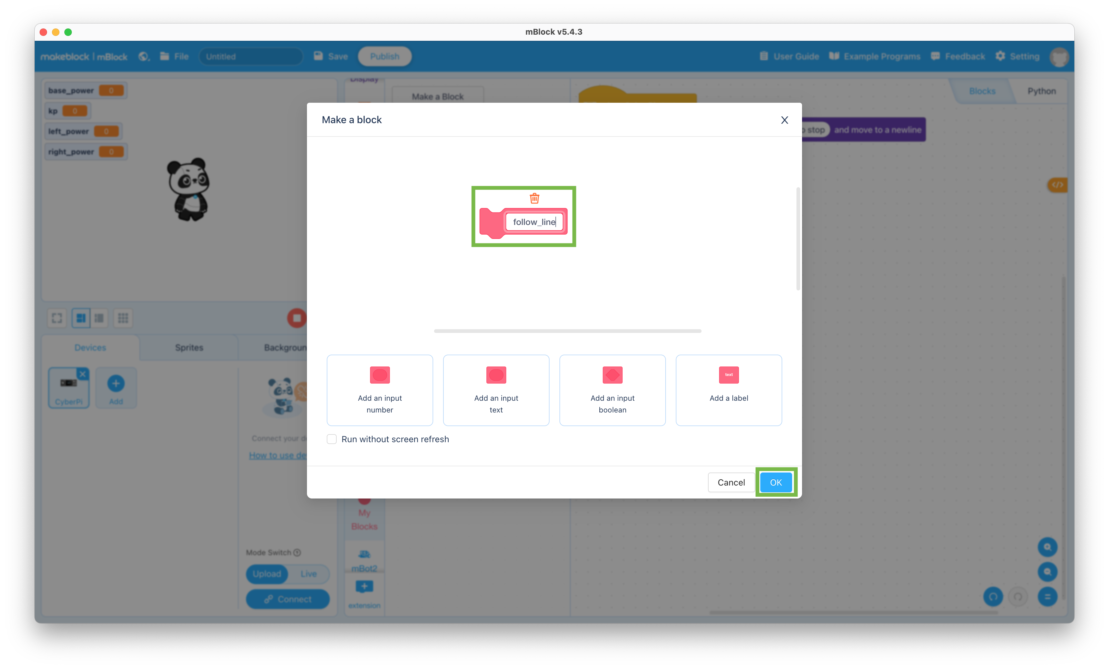
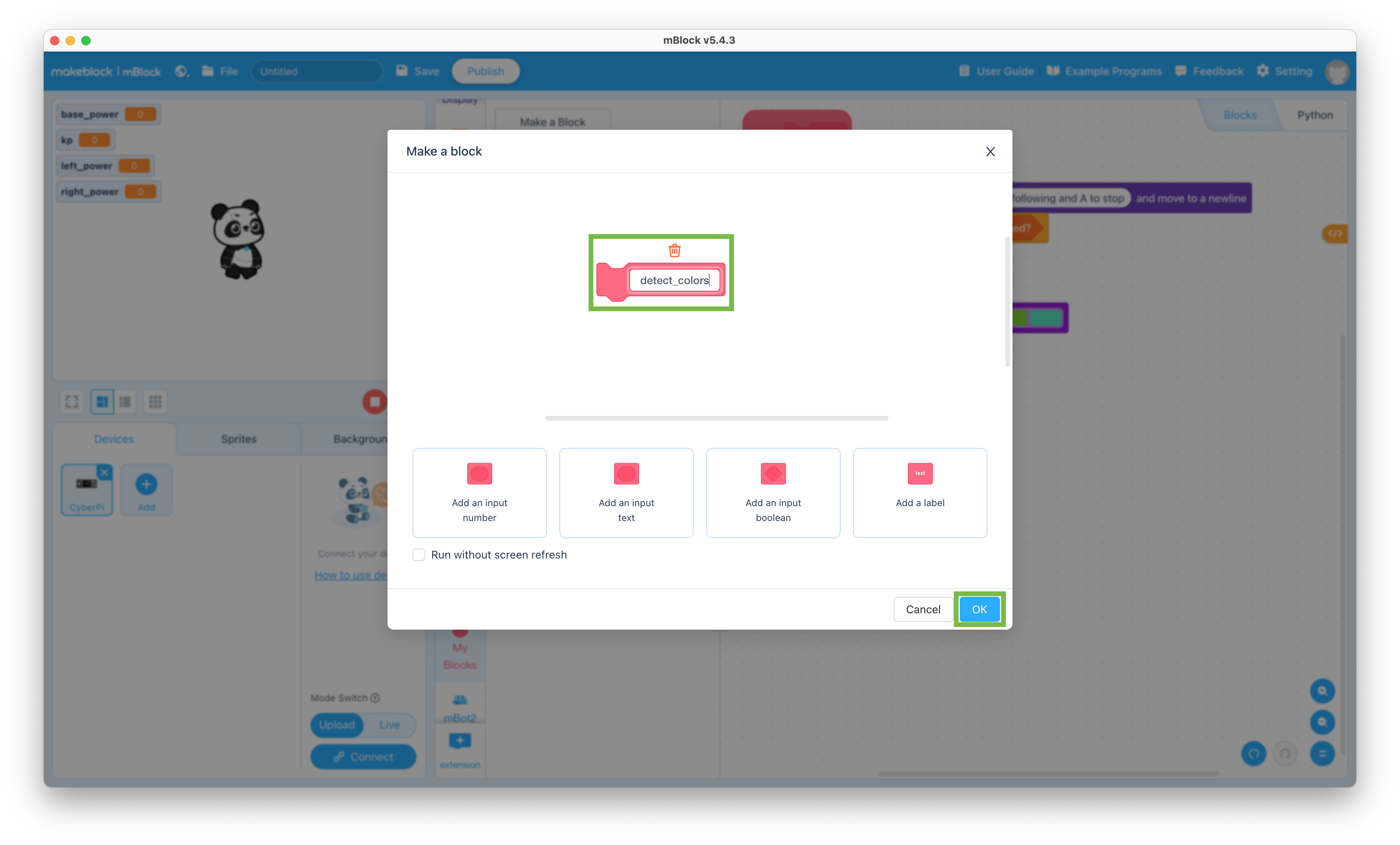
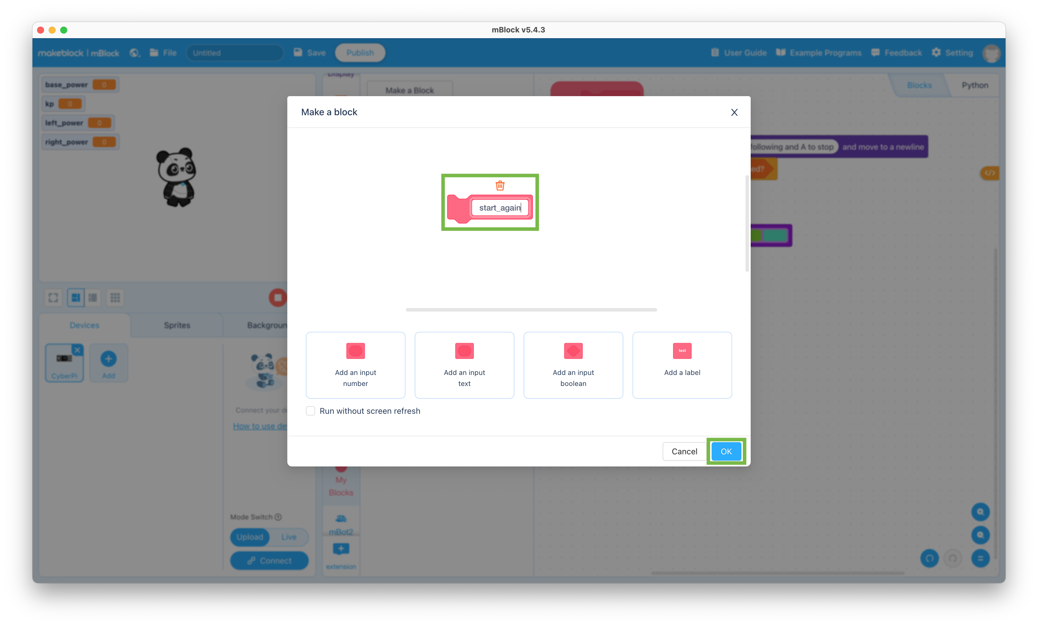
  21. Click the My Blocks selector and click the Make a Block button to create the following blocks

    This will allow you to make your program neater

    Create Blocks

    1. follow_line

      Create line_following block

    2. detect_colors

      Create enter_station block

    3. start_again

      Create start_again block

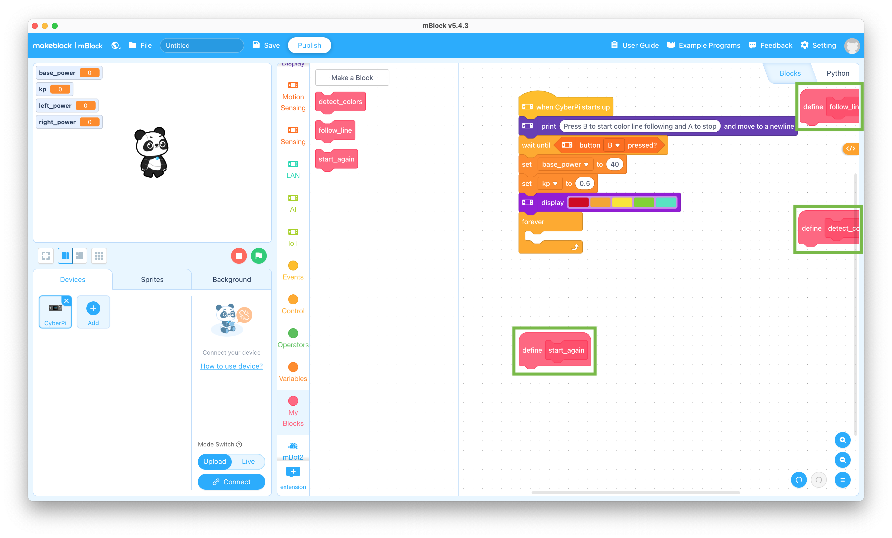
  22. Drag the Define blocks in the coding pane to blank areas

    Define blocks

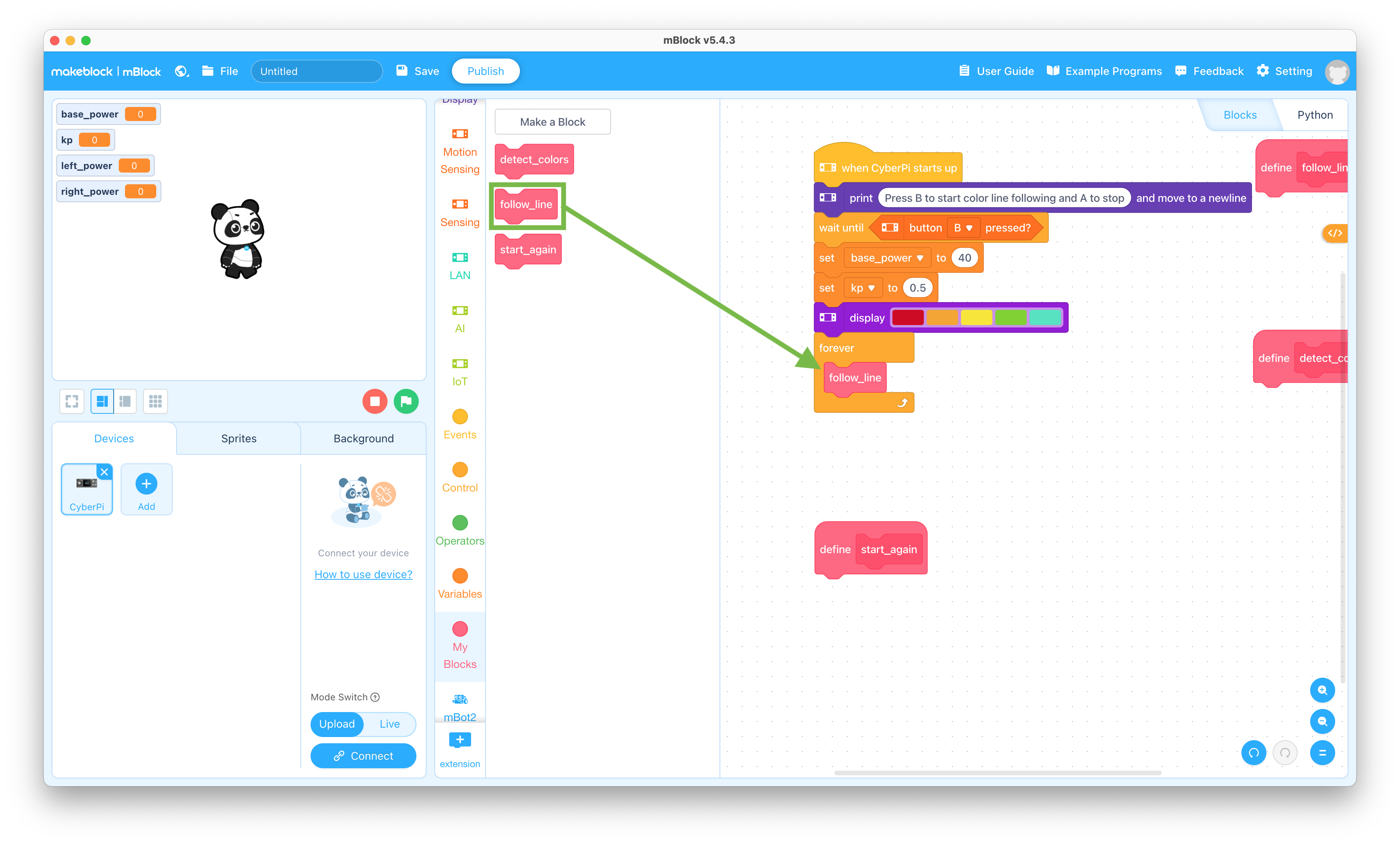
  23. Drag the “follow_line” block to the coding pane and snap it into the forever block

    follow_line block

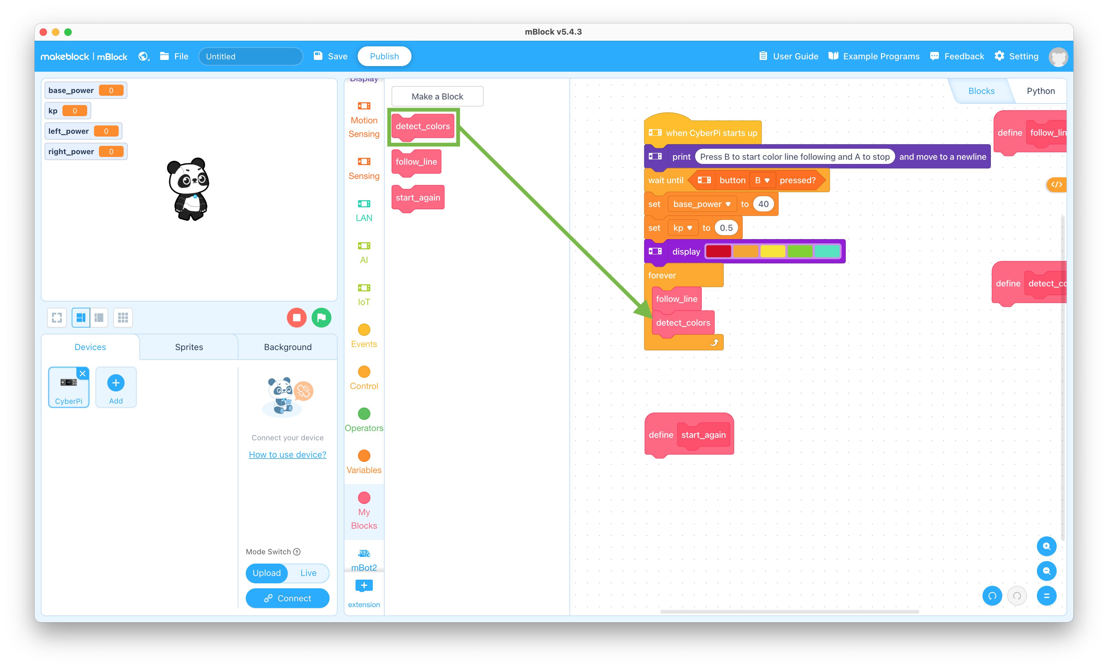
  24. Drag the “detect_colors” block to the coding pane and snap it into the forever block

    detect_colors block

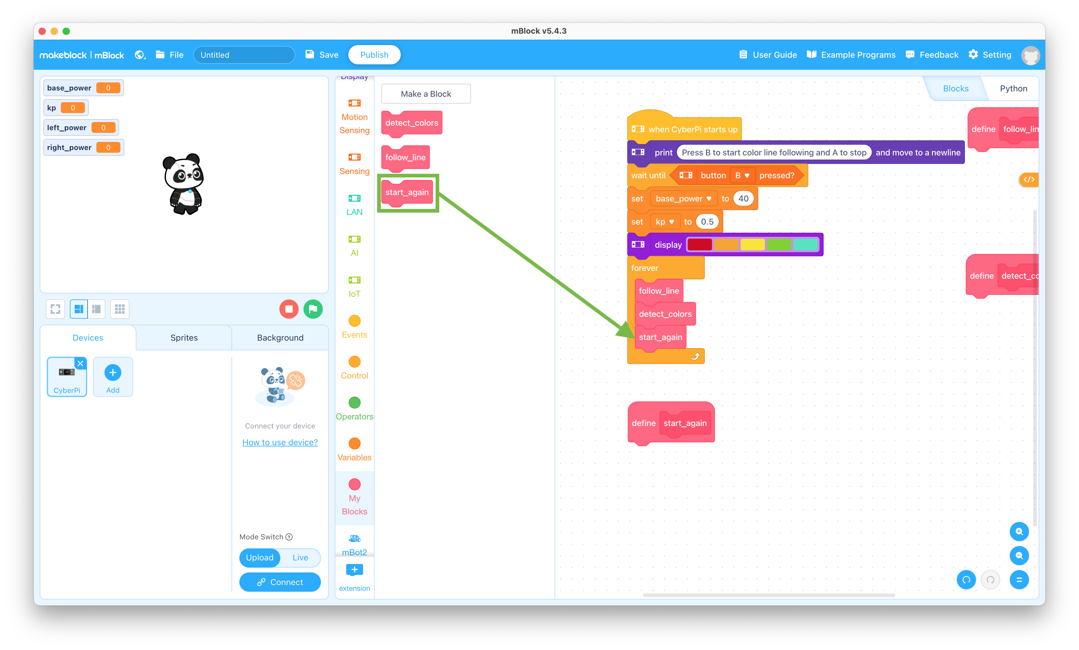
  25. Drag the “start_again” block to the coding pane and snap it into the forever block

    start_again block

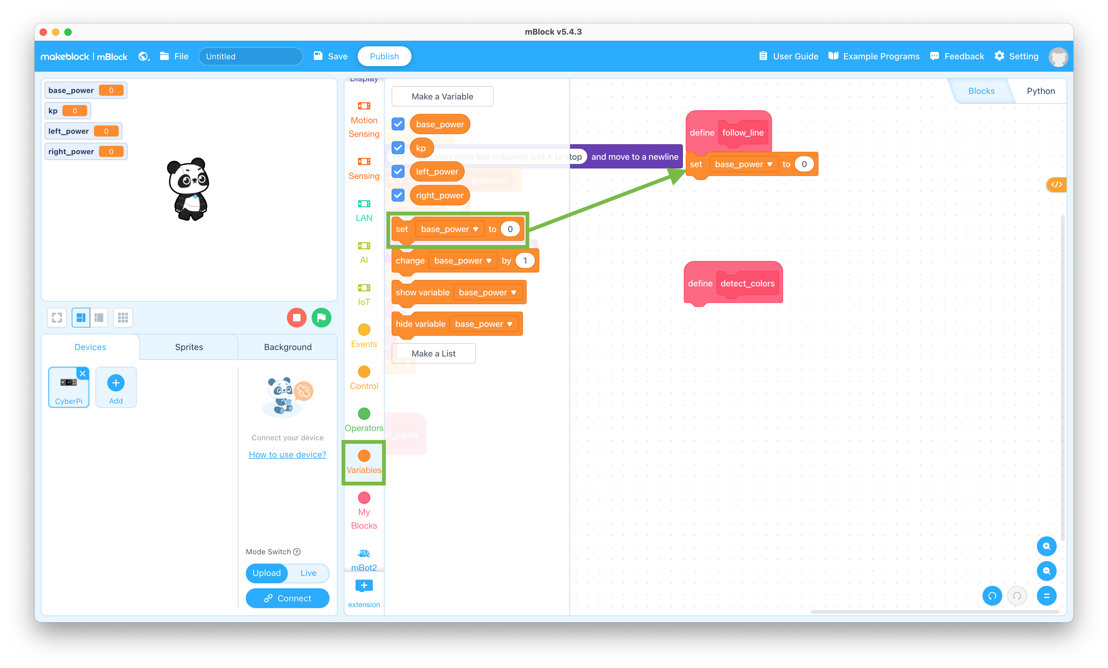
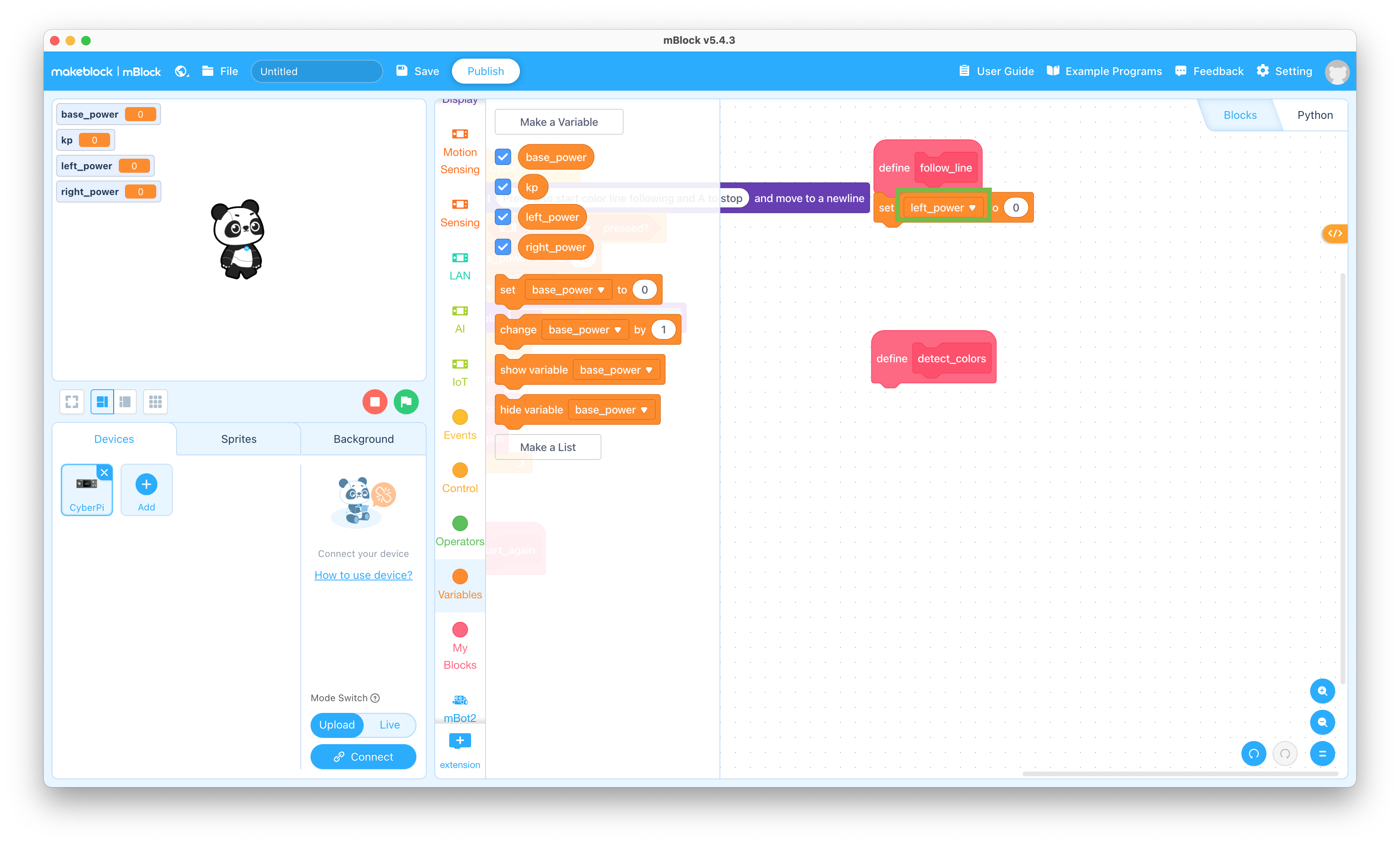
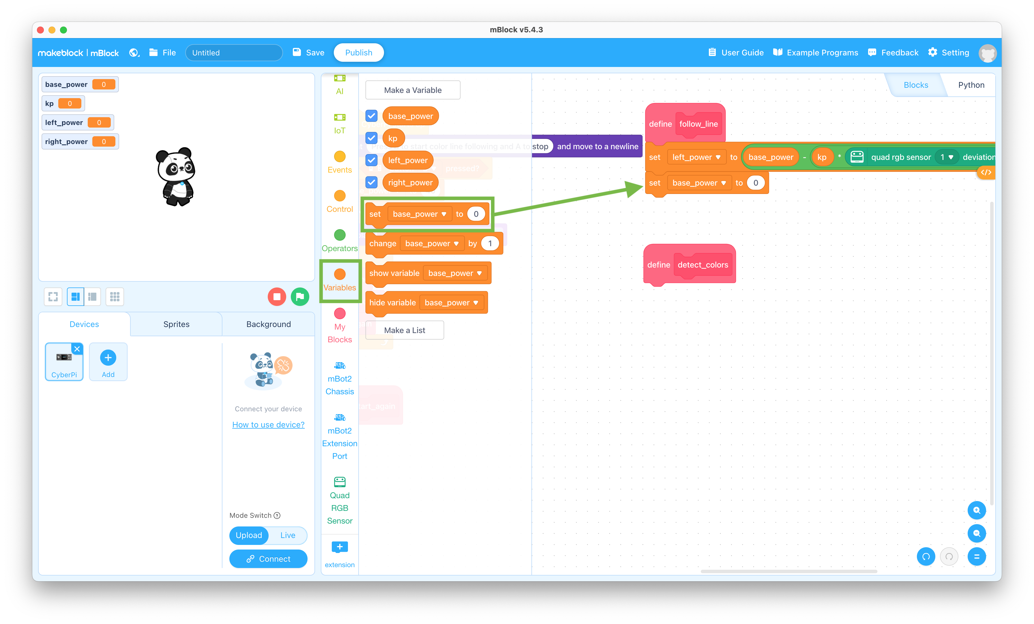
  26. Click the Variables selector and drag the “set base_power to 0” block to the coding pane and snap it to the bottom of the Define follow_line block

    Set variable block

  27. Change the “base_power” to “left_power” in the “set base_power to 0” block

    Set left_power value

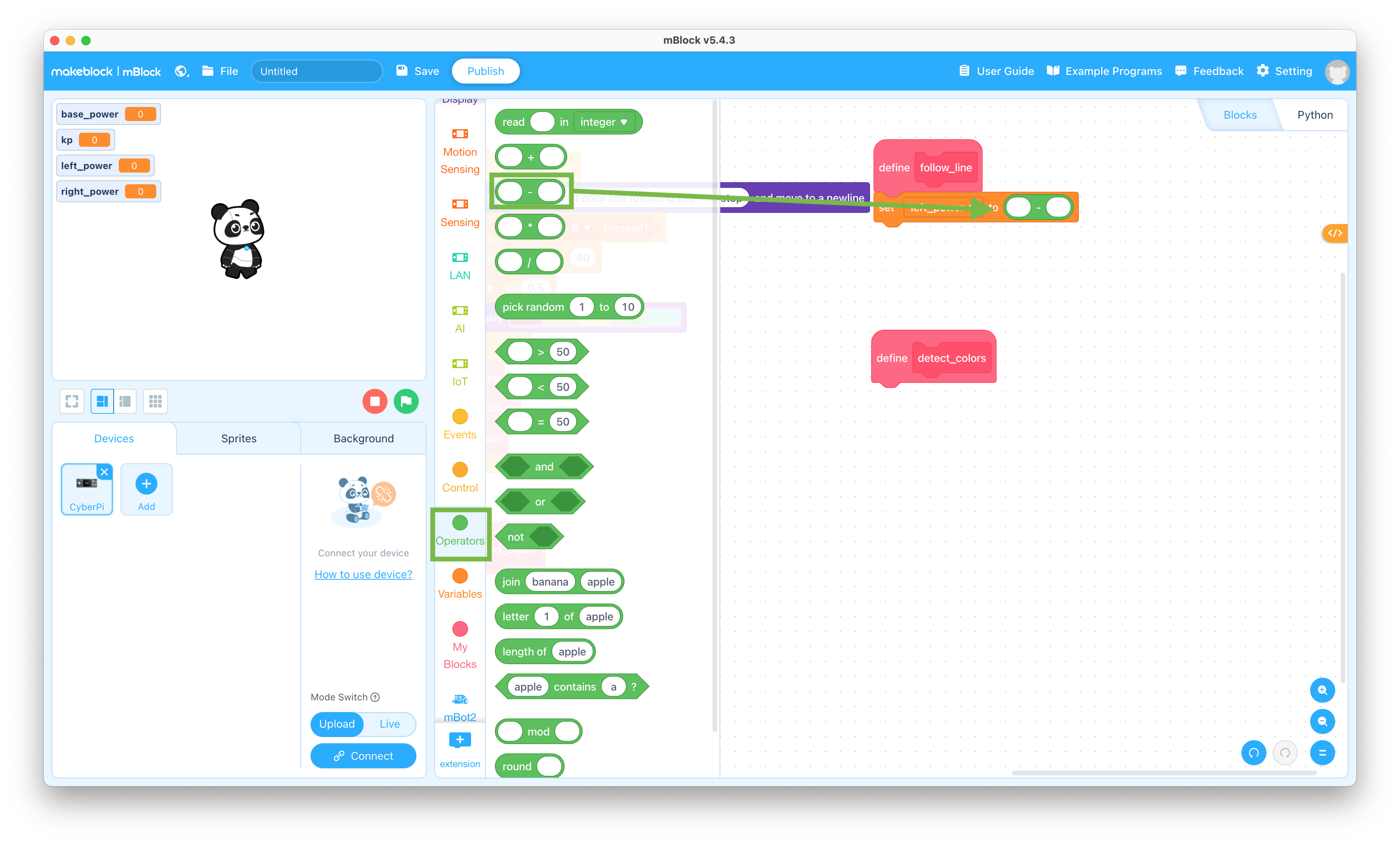
  28. Click the Operators selector and drag the “( ) - ( )” block to the coding pane and snap it into the “set left_power to 0” block

    Subtract operator block

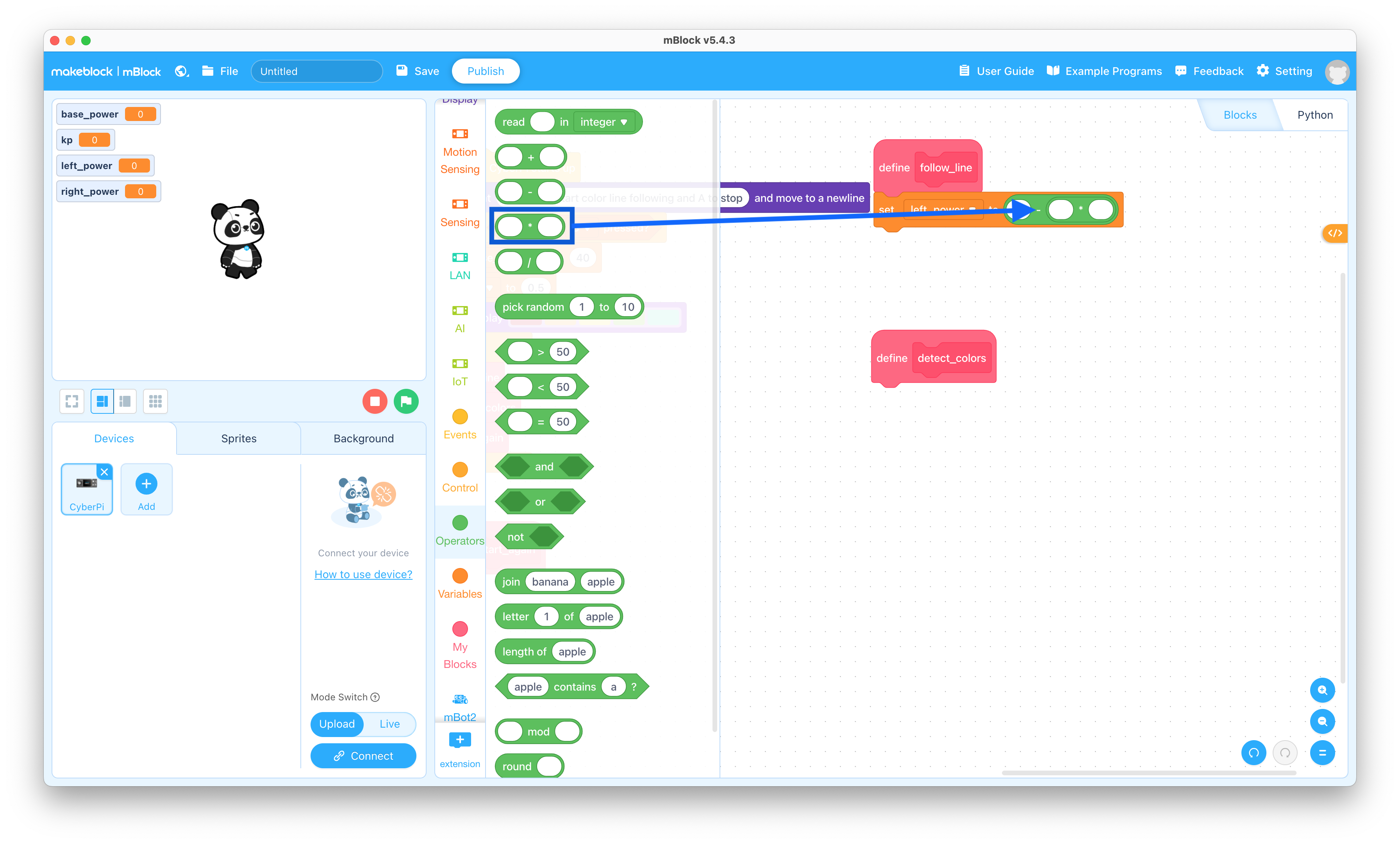
  29. Drag the “( ) * ( )” block to the coding pane and snap it into the right side of the “set left_power to ( ) - ( )” block

    Multiply operator block

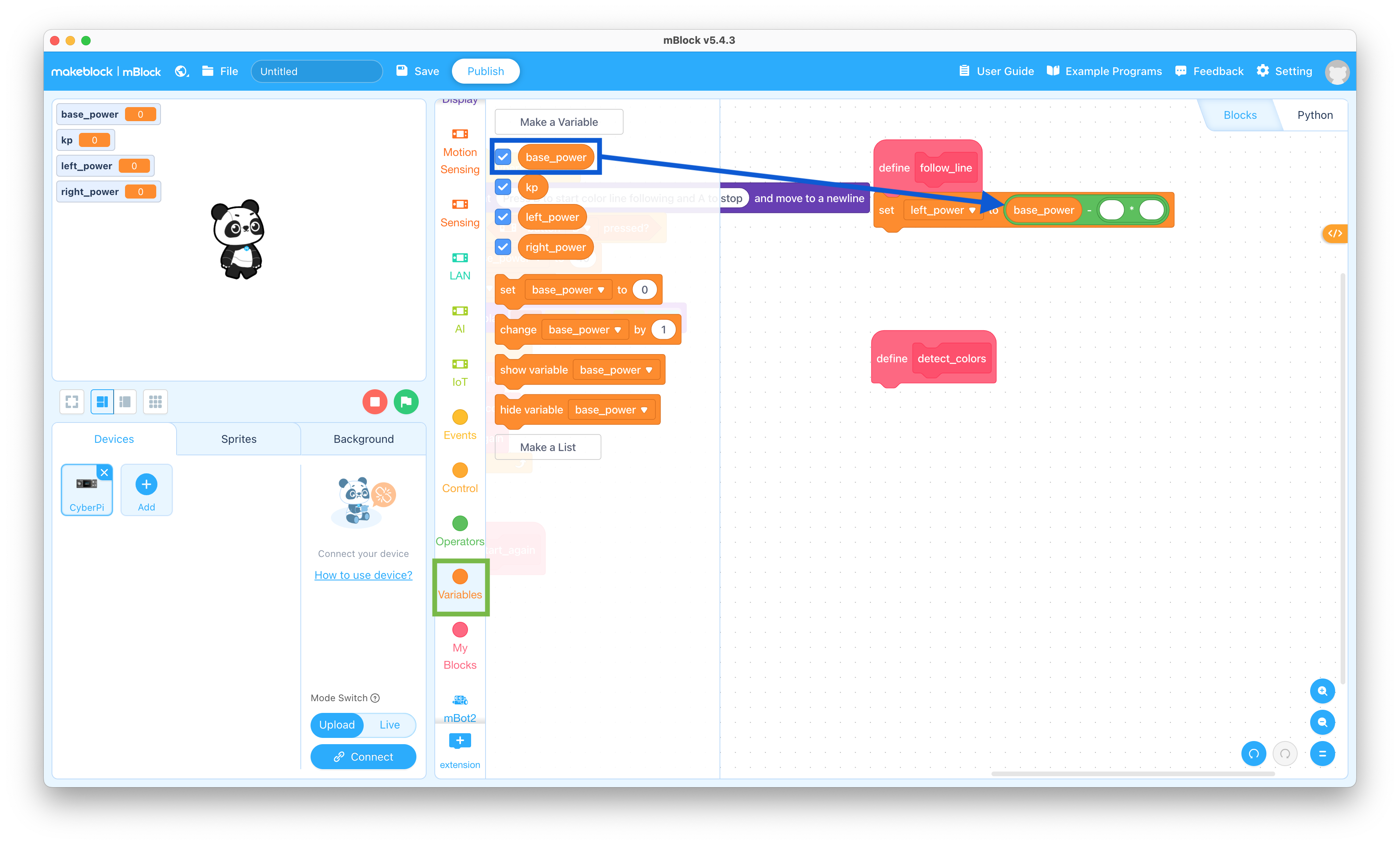
  30. Click the Variables selector and drag the “base_power” block to the coding pane and snap it into the left side of the “set left_power to ( ) - ( ( ) * ( ) )” block

    base_power variable block

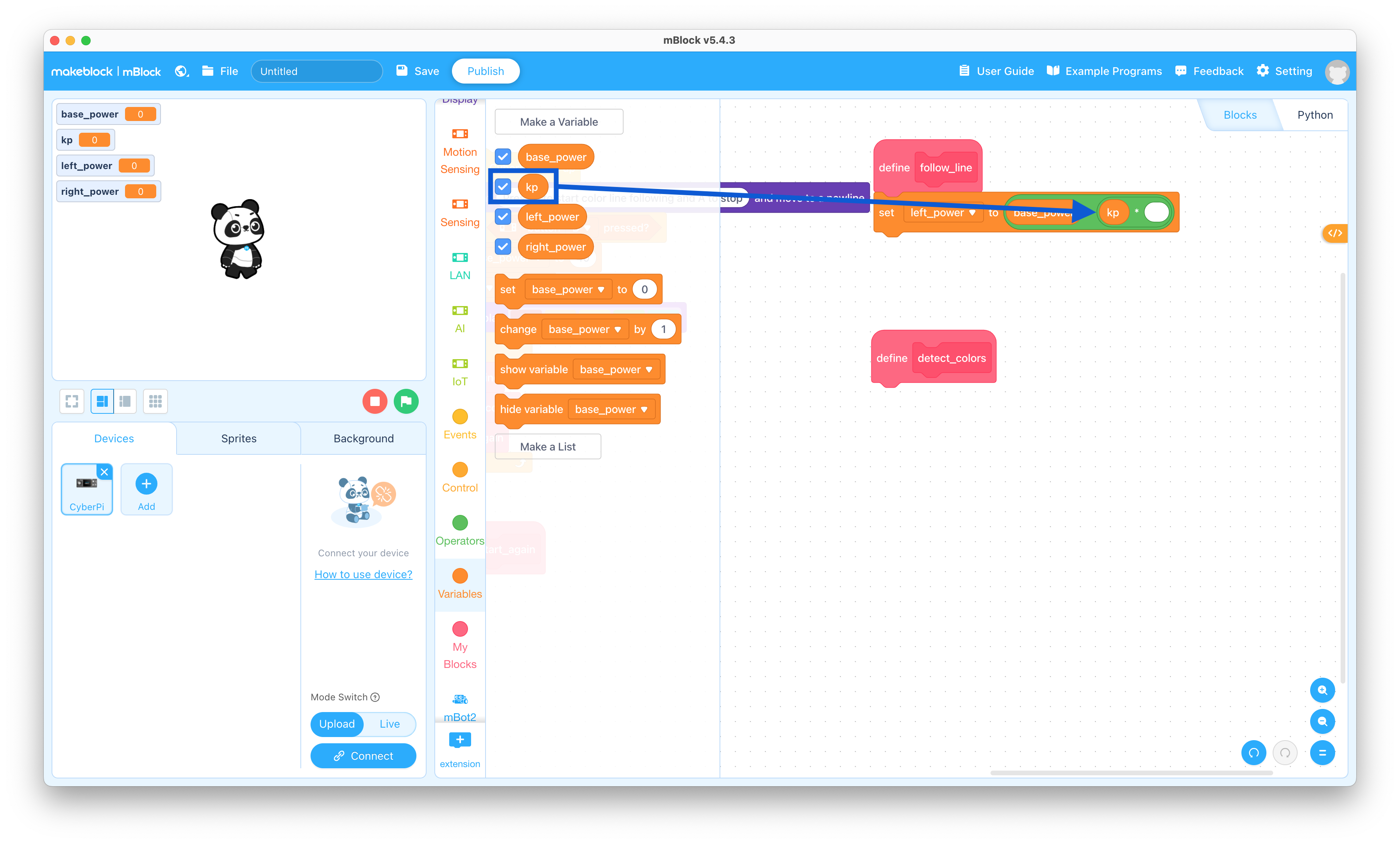
  31. Drag the “kp” block to the coding pane and snap it into the middle of the “set left_power to (base_power) - ( ( ) * ( ) )” block

    kp variable block

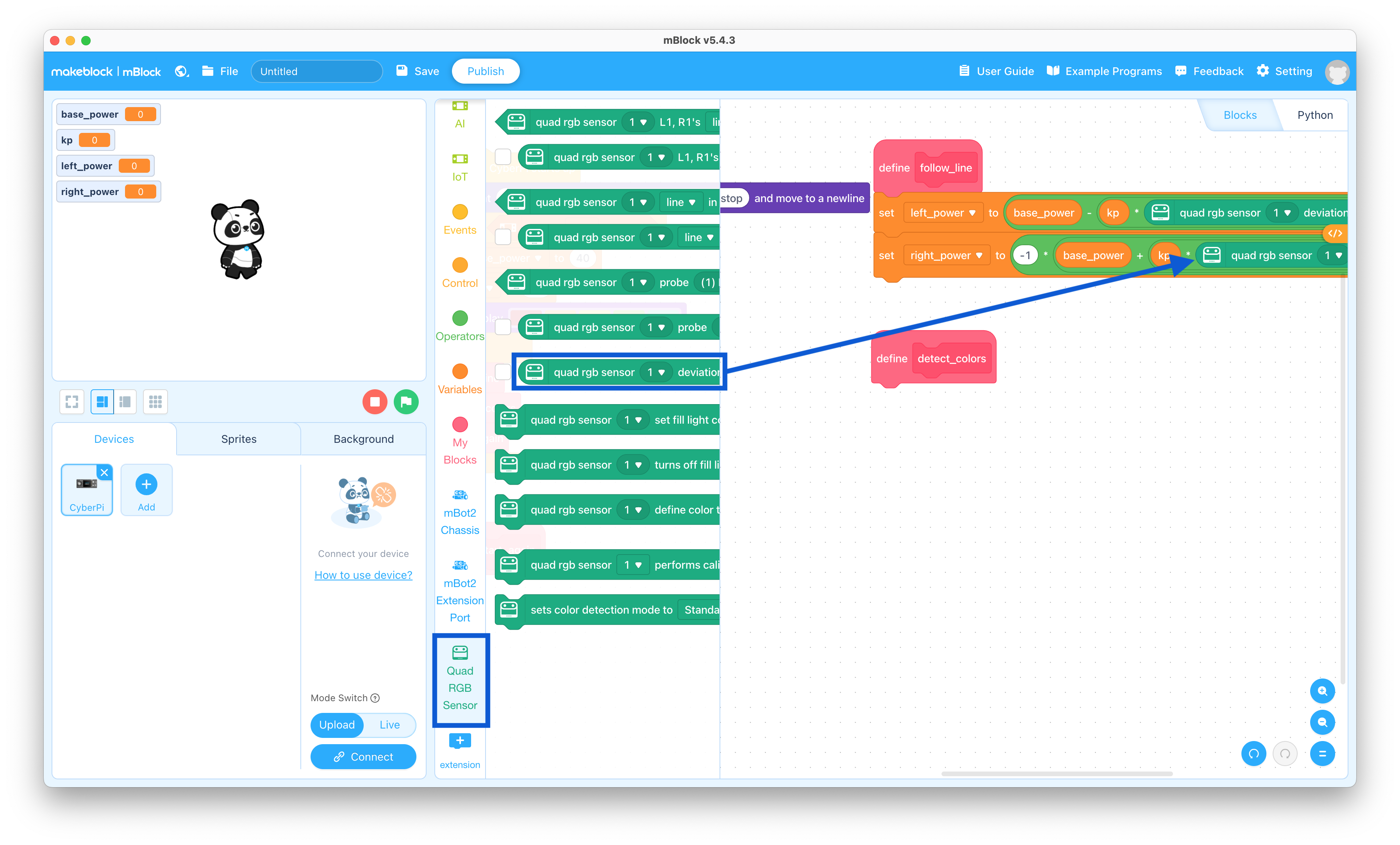
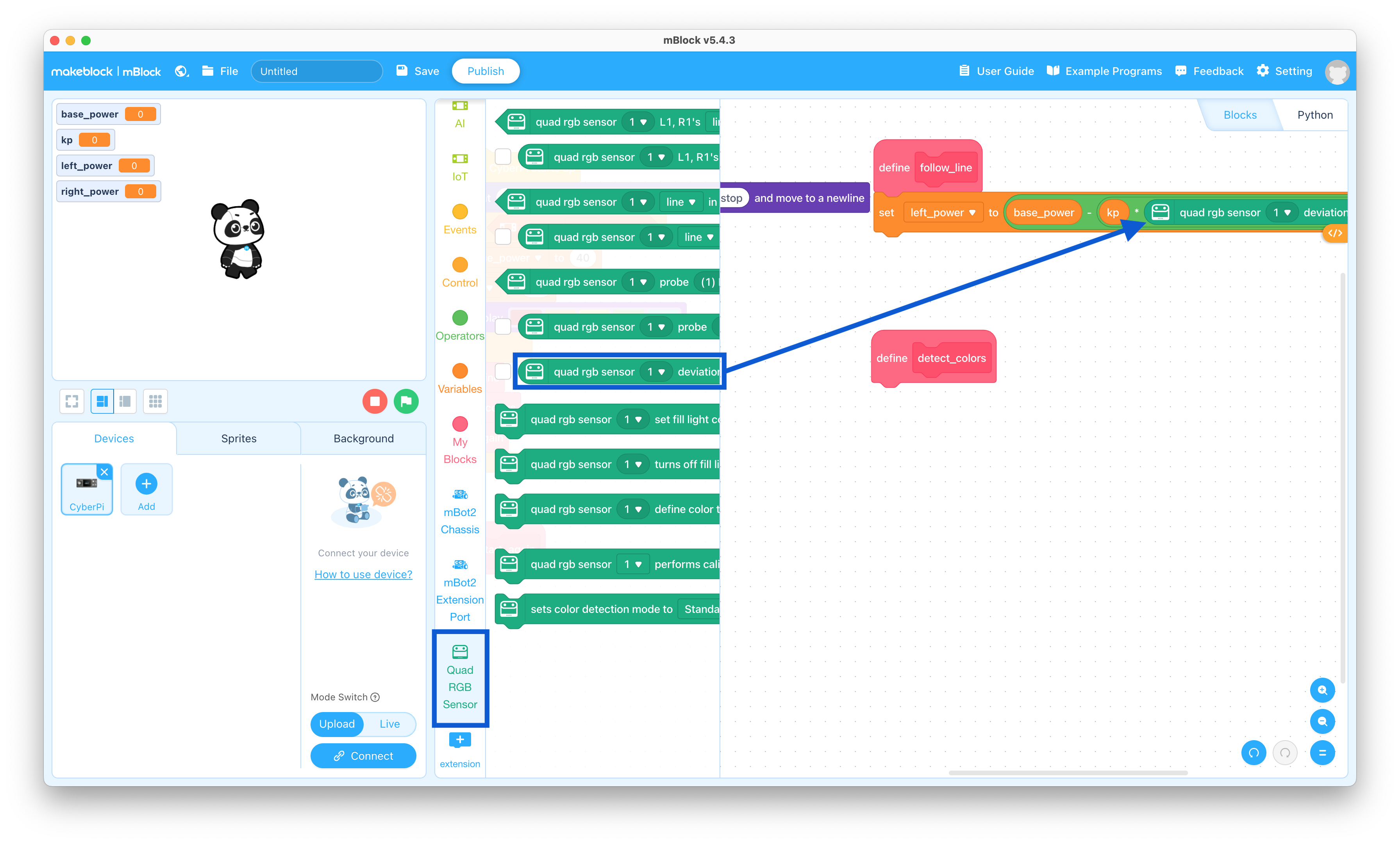
  32. Click the Quad RGB Sensor selector and drag the “quad rgb sensor 1 deviation (-100-100)” block to the coding pane and snap it into the right side of the “set left_power to (base_power) - ( (kp) * ( ) )” block

    RGB sensor deviation block

  33. Click the Variables selector and drag the “set base_power to 0” block to the coding pane and snap it to the bottom of the Define line_following stack

    Set variable block

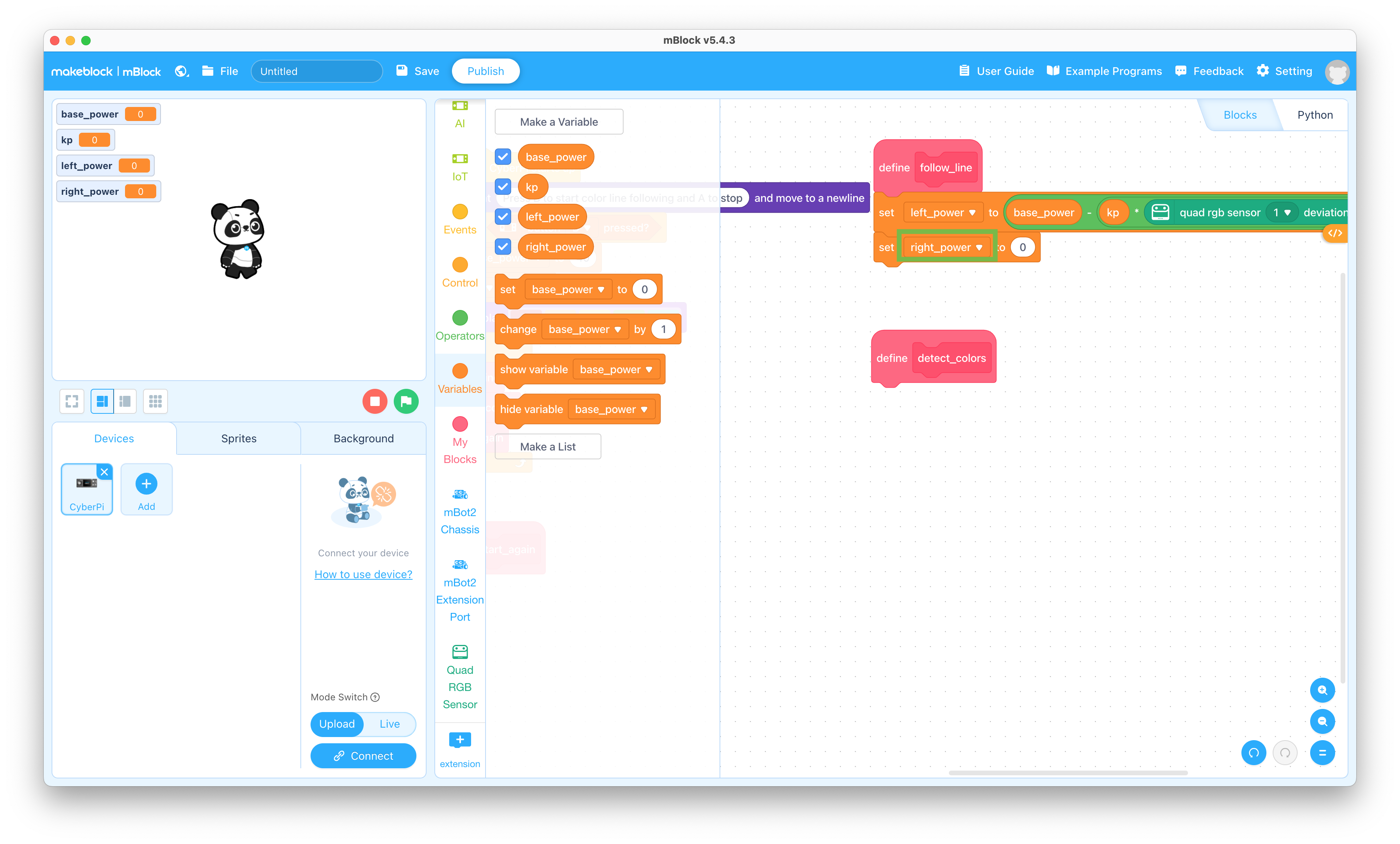
  34. Change the “base_power” to “right_power” in the “set base_power to 0” block

    Set left_power value

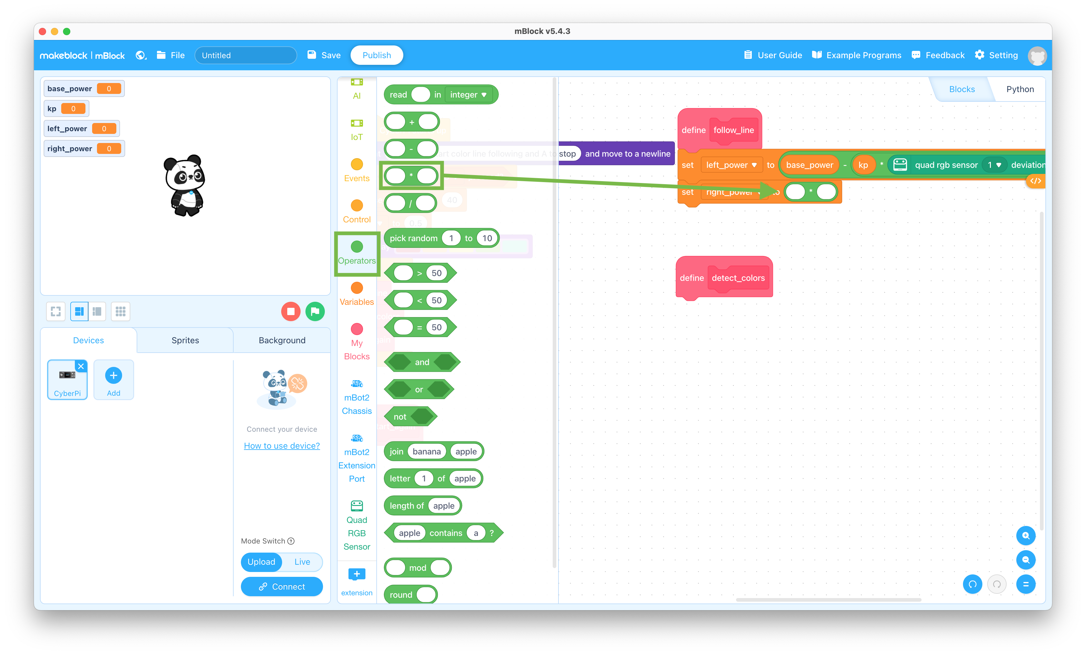
  35. Click the Operators selector and drag the “( ) * ( )” block to the coding pane and snap it into the “set right_power to 0” block

    Multiply operator block

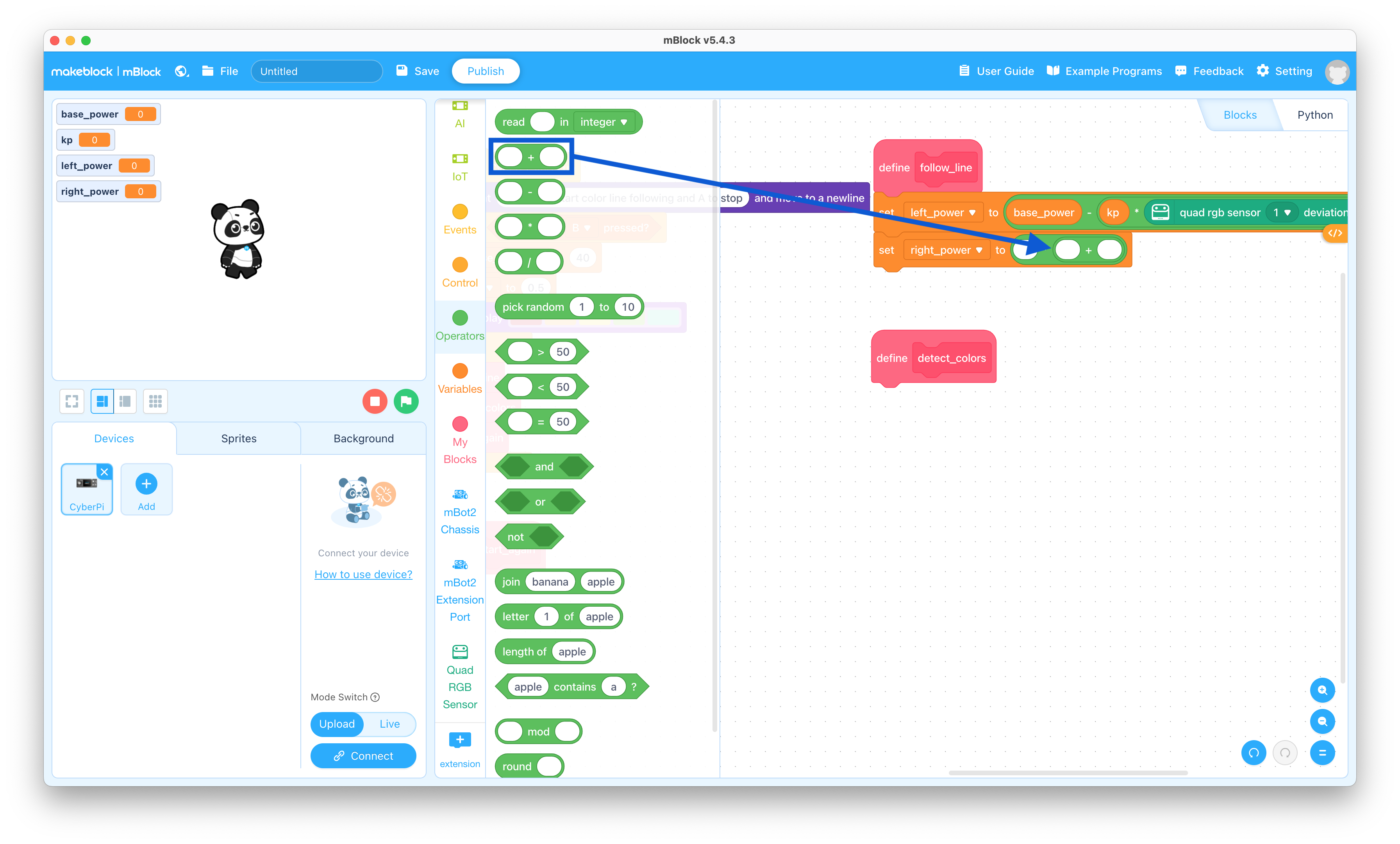
  36. Drag the “( ) + ( )” block to the coding pane and snap it into the right side of the “set right_power to ( ) * ( )” block

    Add operator block

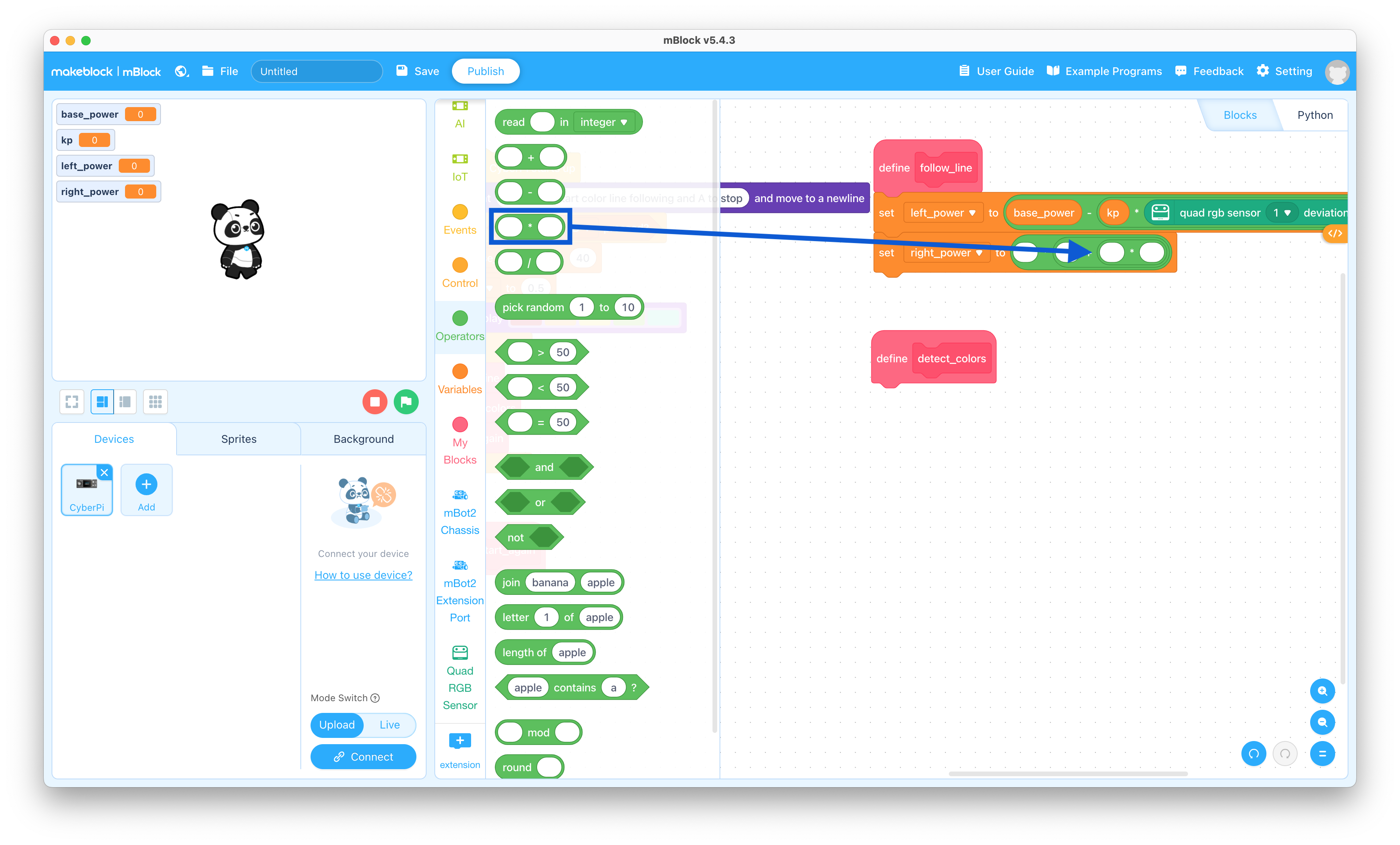
  37. Drag the “( ) * ( )” block to the coding pane and snap it into the right side of the “set right_power to ( ) * ( ( ) + ( ) )” block

    Multiply operator block

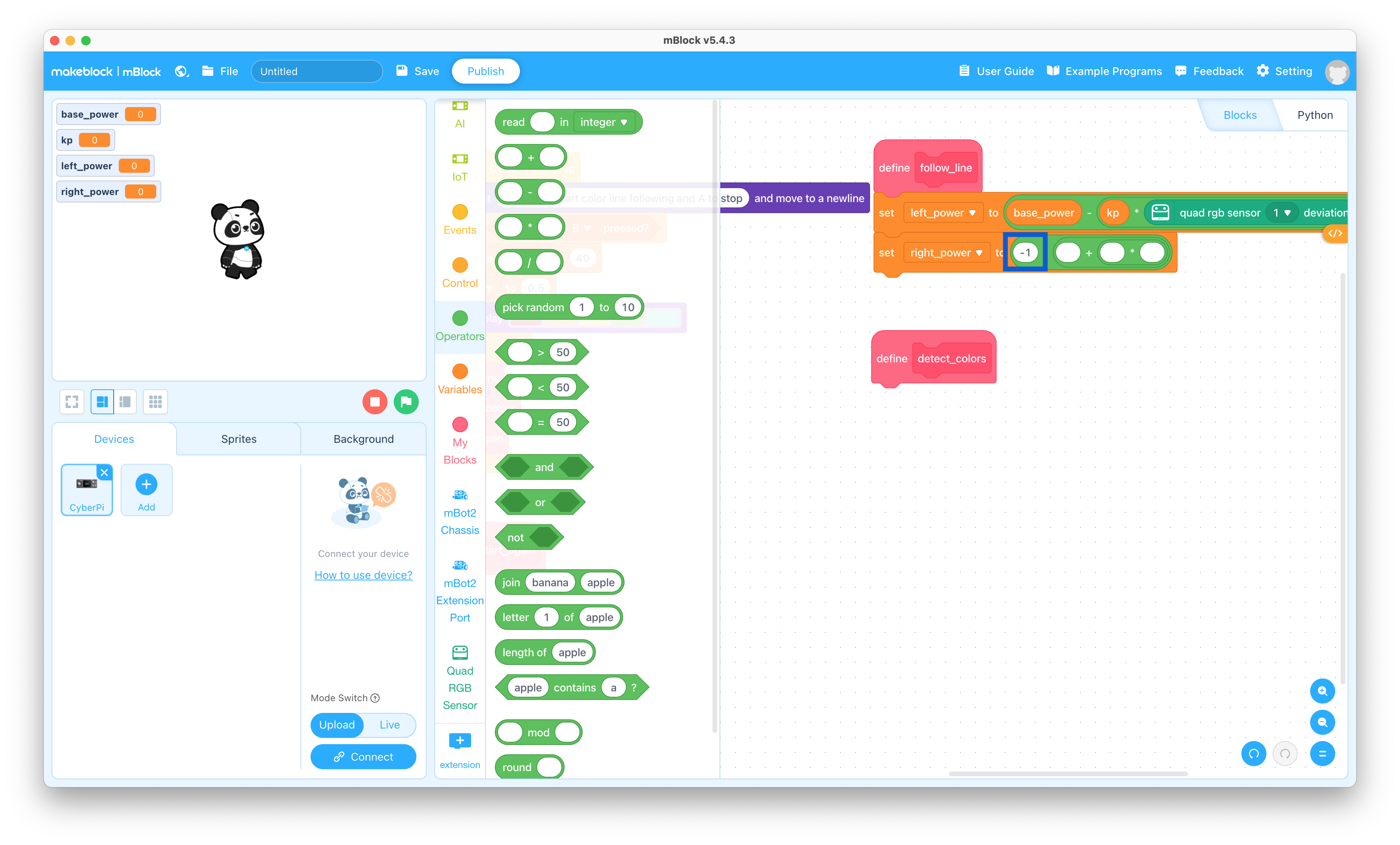
  38. Change the first of the “set right_power to ( ) * ( ( ) + ( ( ) * ( ) ) )” block to “-1”

    base_power variable block

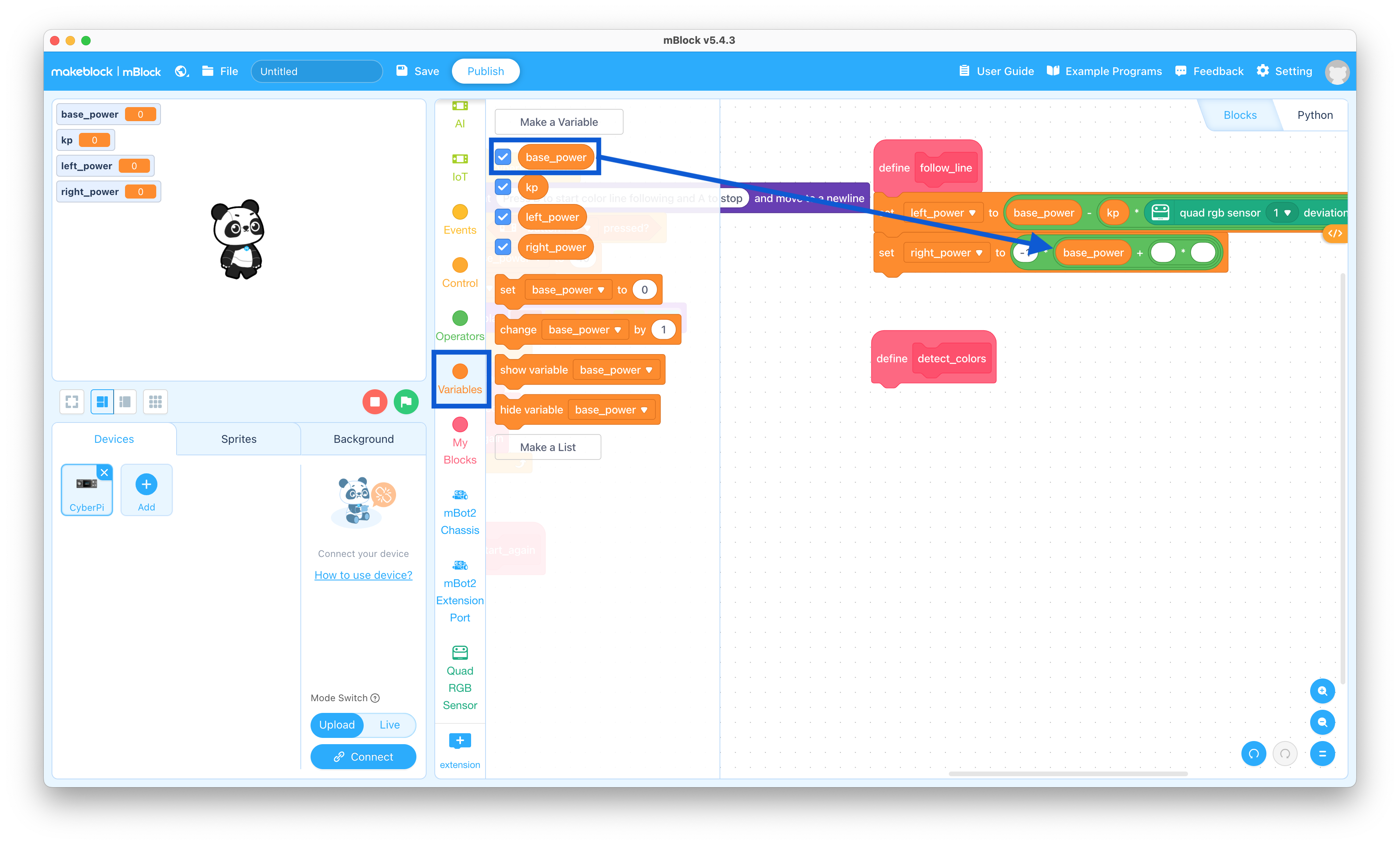
  39. Click the Variables selector and drag the “base_power” block to the coding pane and snap it into the second of the “set right_power to (-1) * ( ( ) + ( ( ) * ( ) ) )” block

    base_power variable block

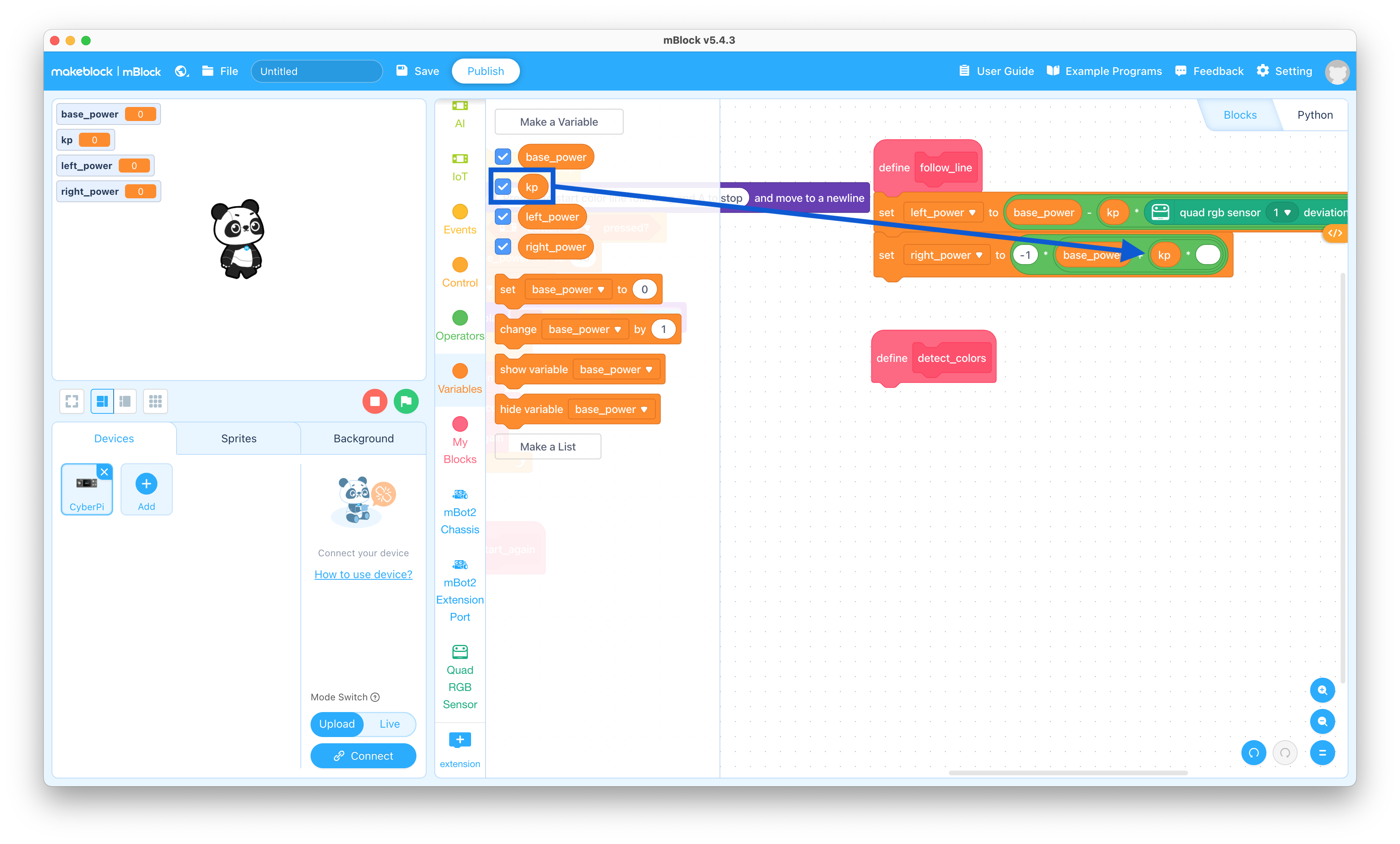
  40. Drag the “kp” block to the coding pane and snap it into the third of the “set right_power to (-1) * ( (base_power) + ( ( ) * ( ) ) )” block

    kp variable block

  41. Click the Quad RGB Sensor selector and drag the “quad rgb sensor 1 deviation (-100-100)” block to the coding pane and snap it into the right side of the “set right_power to (-1) * ( (base_power) + ( (kp) * ( ) ) )” block

    RGB sensor deviation block

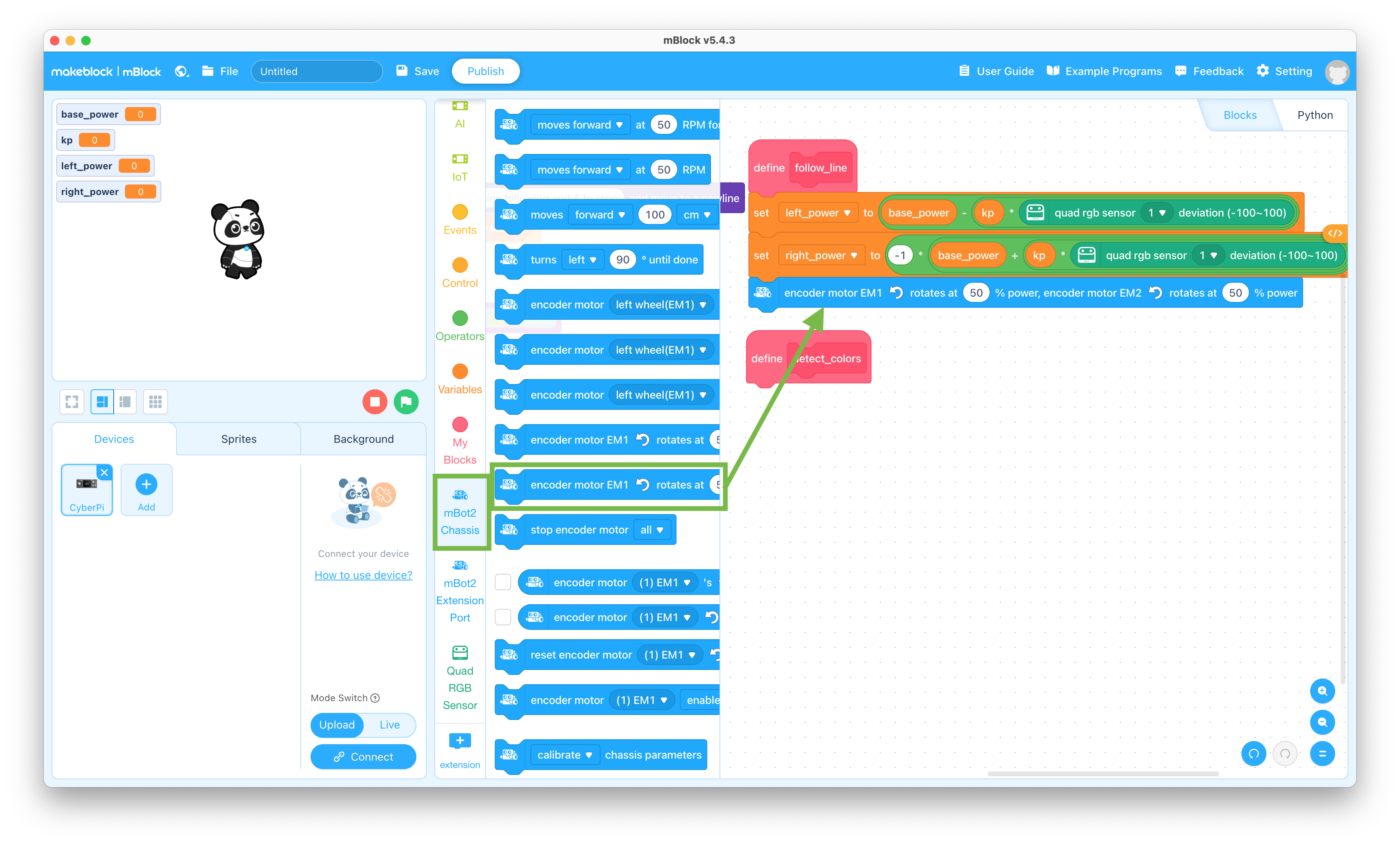
  42. Click the mBot2 Chassis selector and drag the “encoder motor EM1 rotates at 50% power, encoder motor EM2 rotates at 50% power” block to the coding pane and snap it to the bottom of the Define line_following stack

    Move motors block

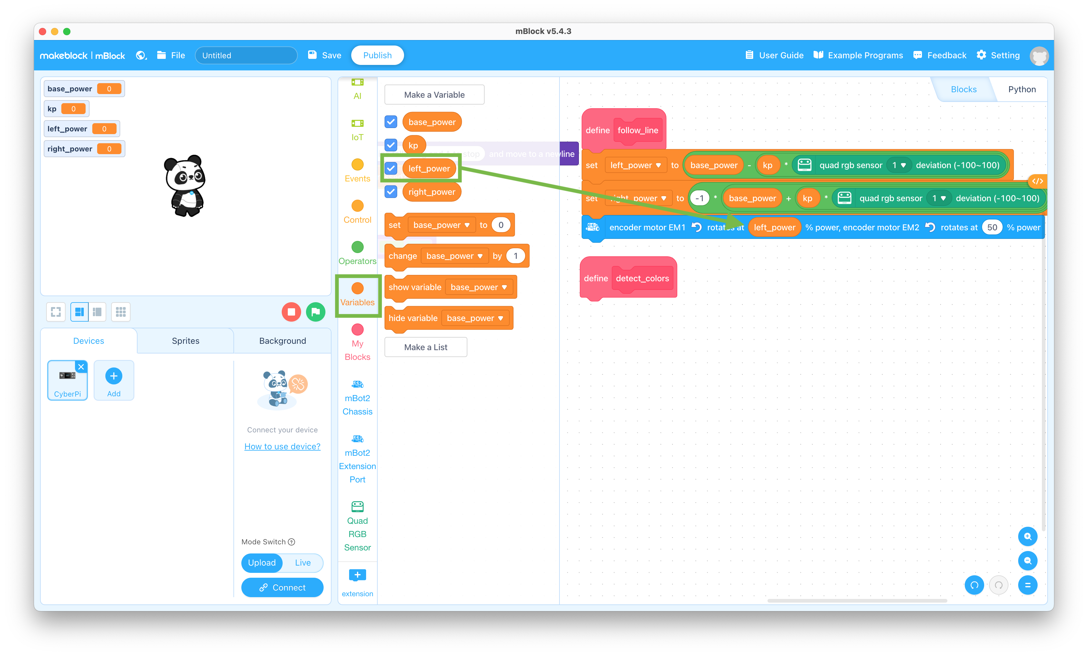
  43. Click the Variables selector and drag the “left_power” block to the coding pane and snap it into the left section of the “encoder motor EM1 rotates at 50% power, encoder motor EM2 rotates at 50% power” block

    left_power variable block

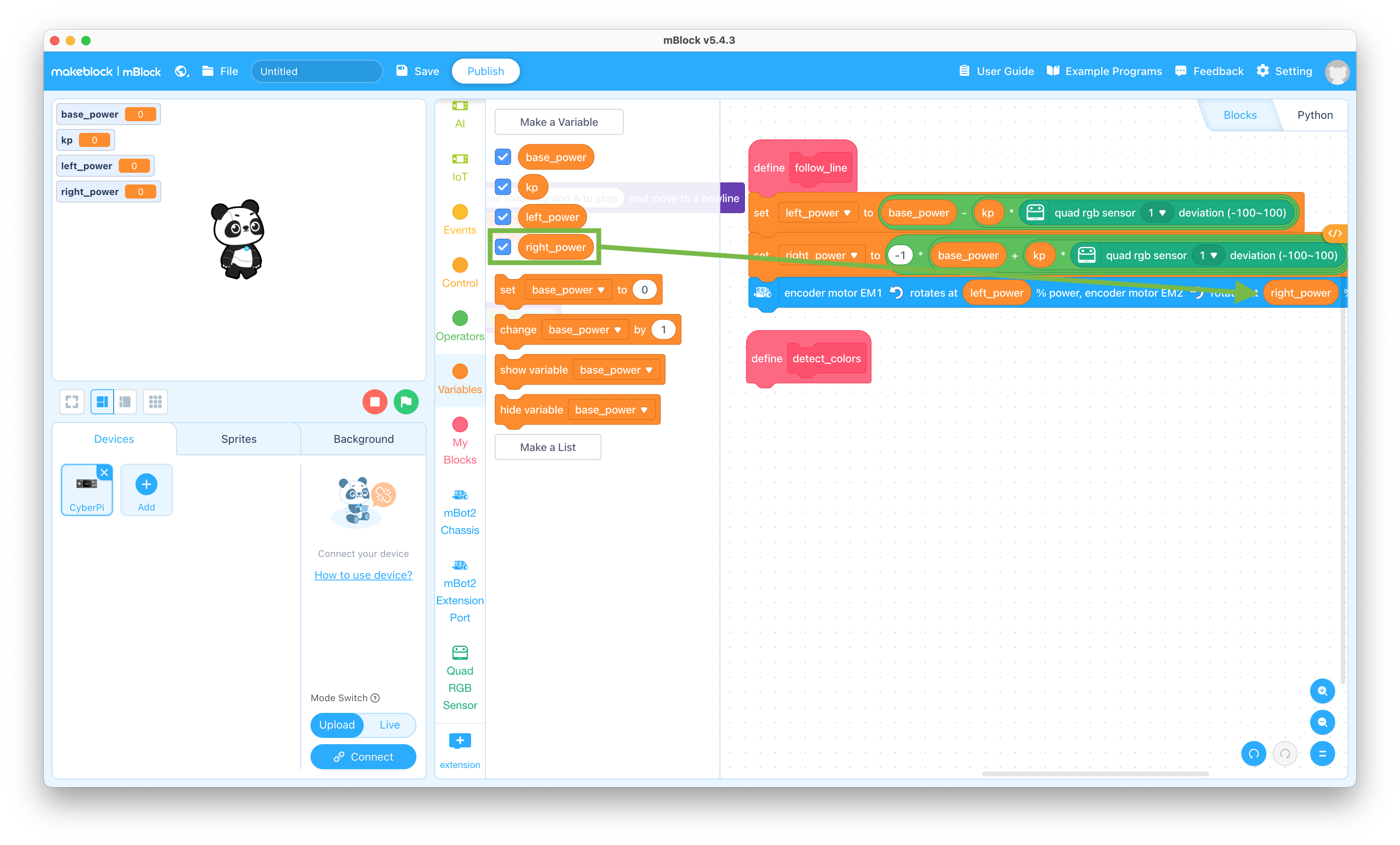
  44. Drag the “right_power” block to the coding pane and snap it into the right section of the “encoder motor EM1 rotates at left_power% power, encoder motor EM2 rotates at 50% power” block

    right_power variable block

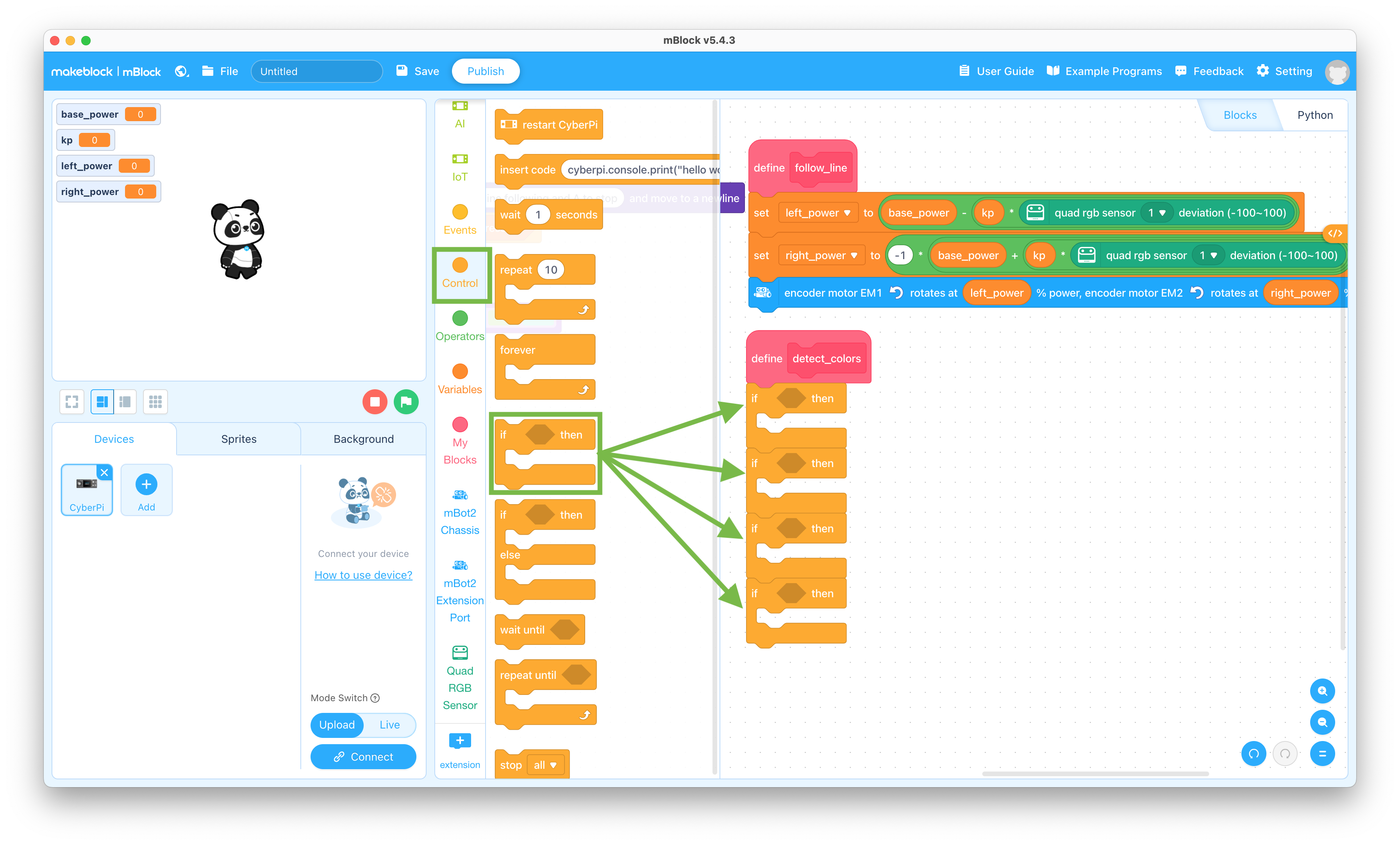
  45. Click the Control selector and drag the “if < > then” block to the coding pane and snap it to the bottom of the Define detect_colors block 4 times

    If-then block

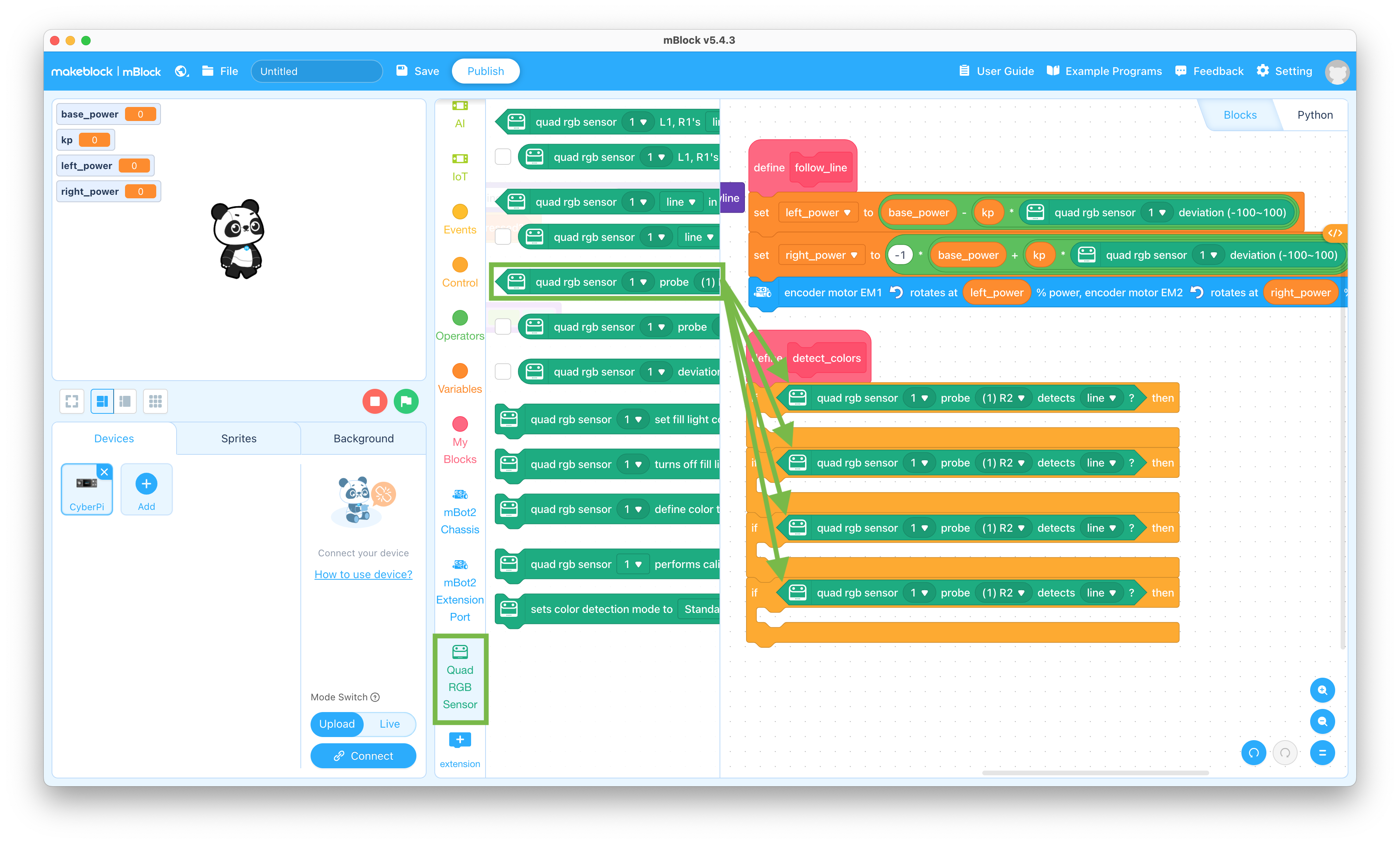
  46. Click the Quad RGB Sensor selector and drag the “quad rgb sensor 1 probe (1) R2 detects line?” block to the coding pane and snap it into each of the “if < > then” blocks

    Quad RGB sensor block

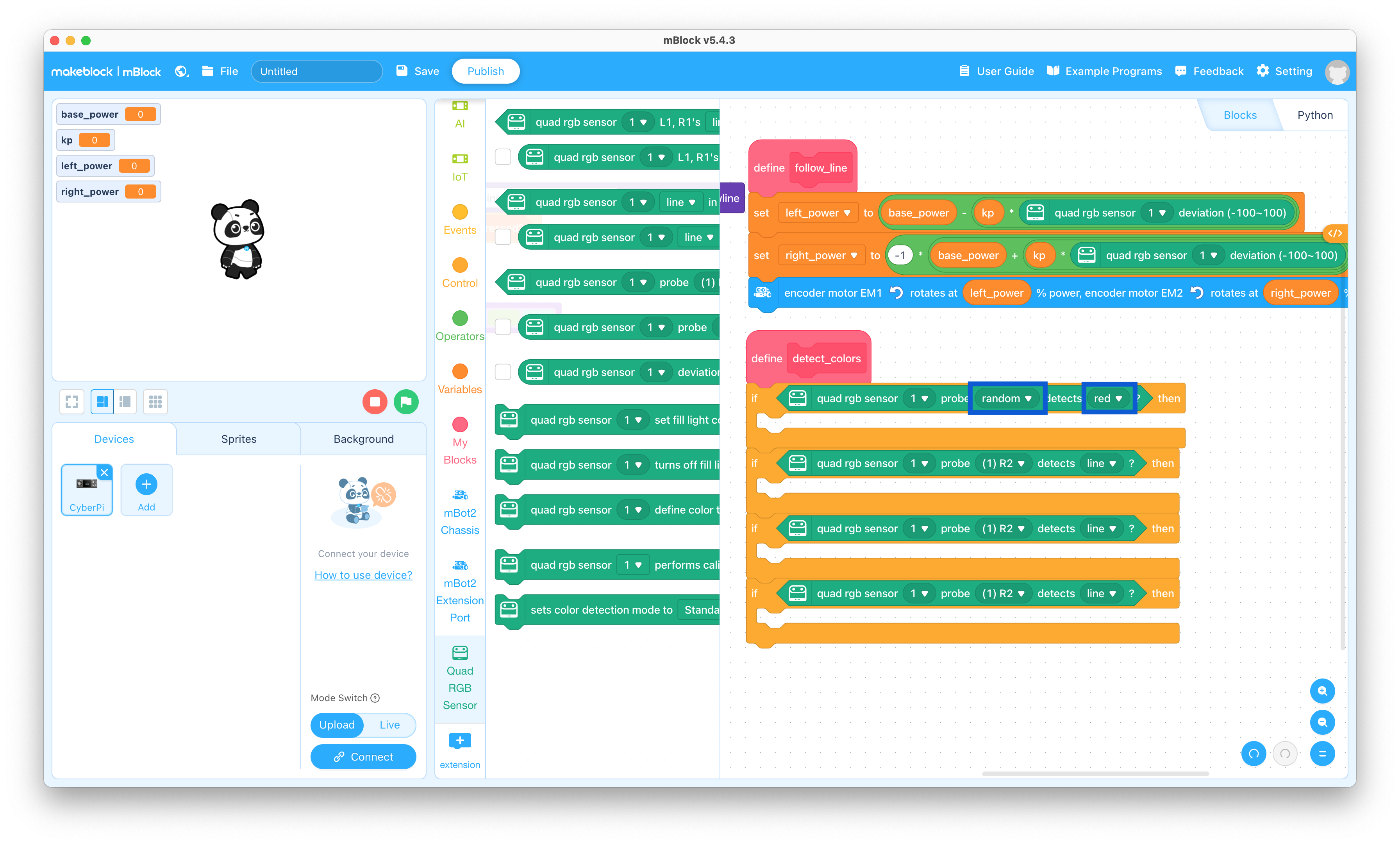
  47. Change the “(1) R2” to “random” and the “line” to “red” in the top “quad rgb sensor 1 probe (1) R2 detects line?” block

    Detect red line

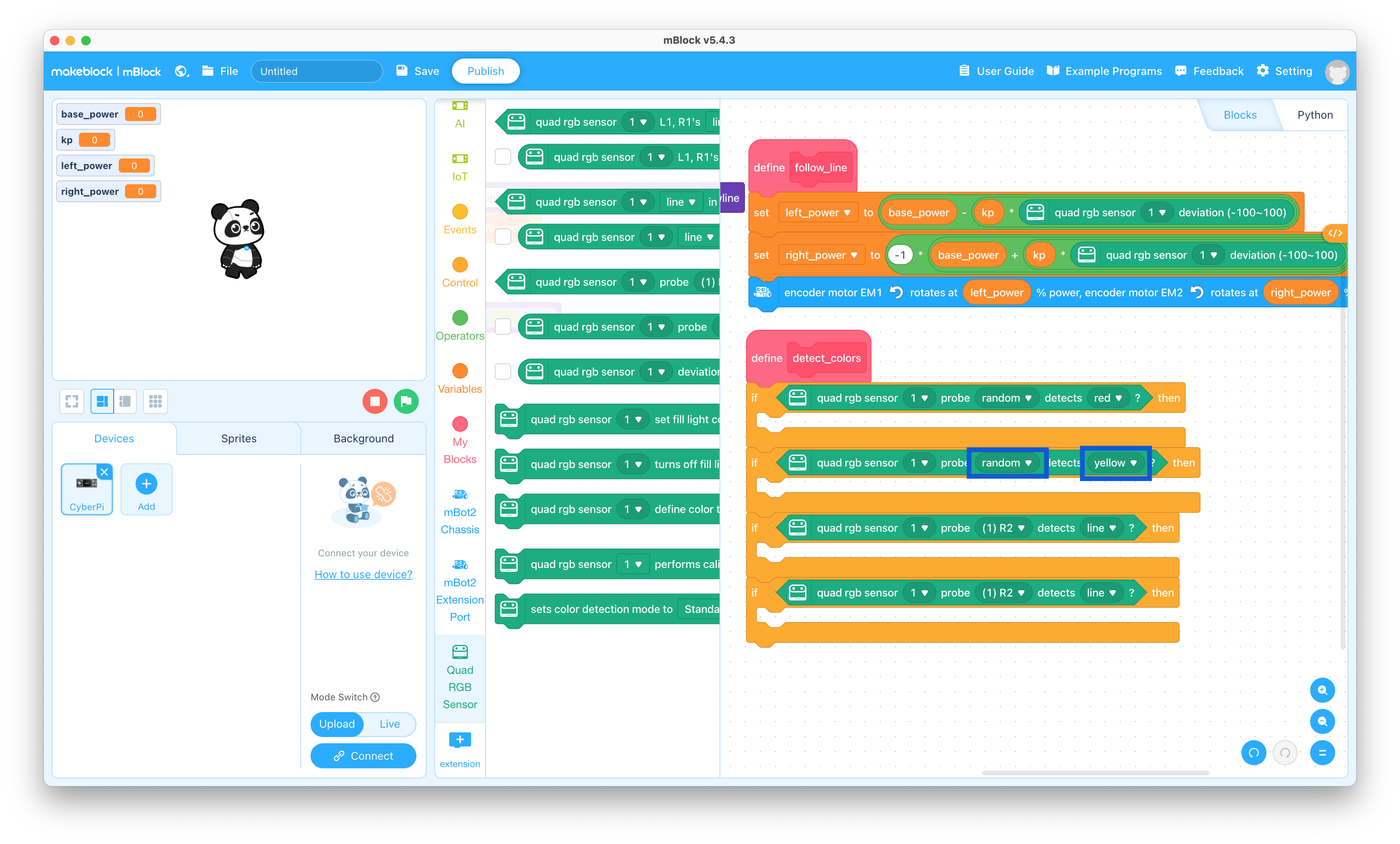
  48. Change the “(1) R2” to “random” and the “line” to “yellow” in the second “quad rgb sensor 1 probe (1) R2 detects line?” block

    Detect yellow line

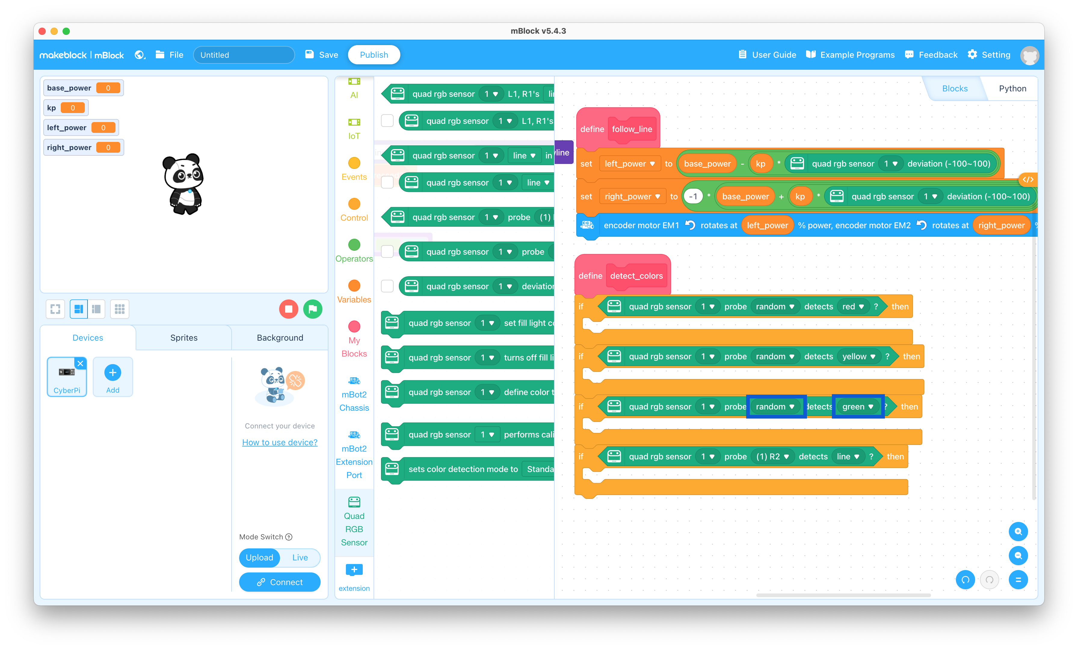
  49. Change the “(1) R2” to “random” and the “line” to “green” in the third “quad rgb sensor 1 probe (1) R2 detects line?” block

    Detect green line

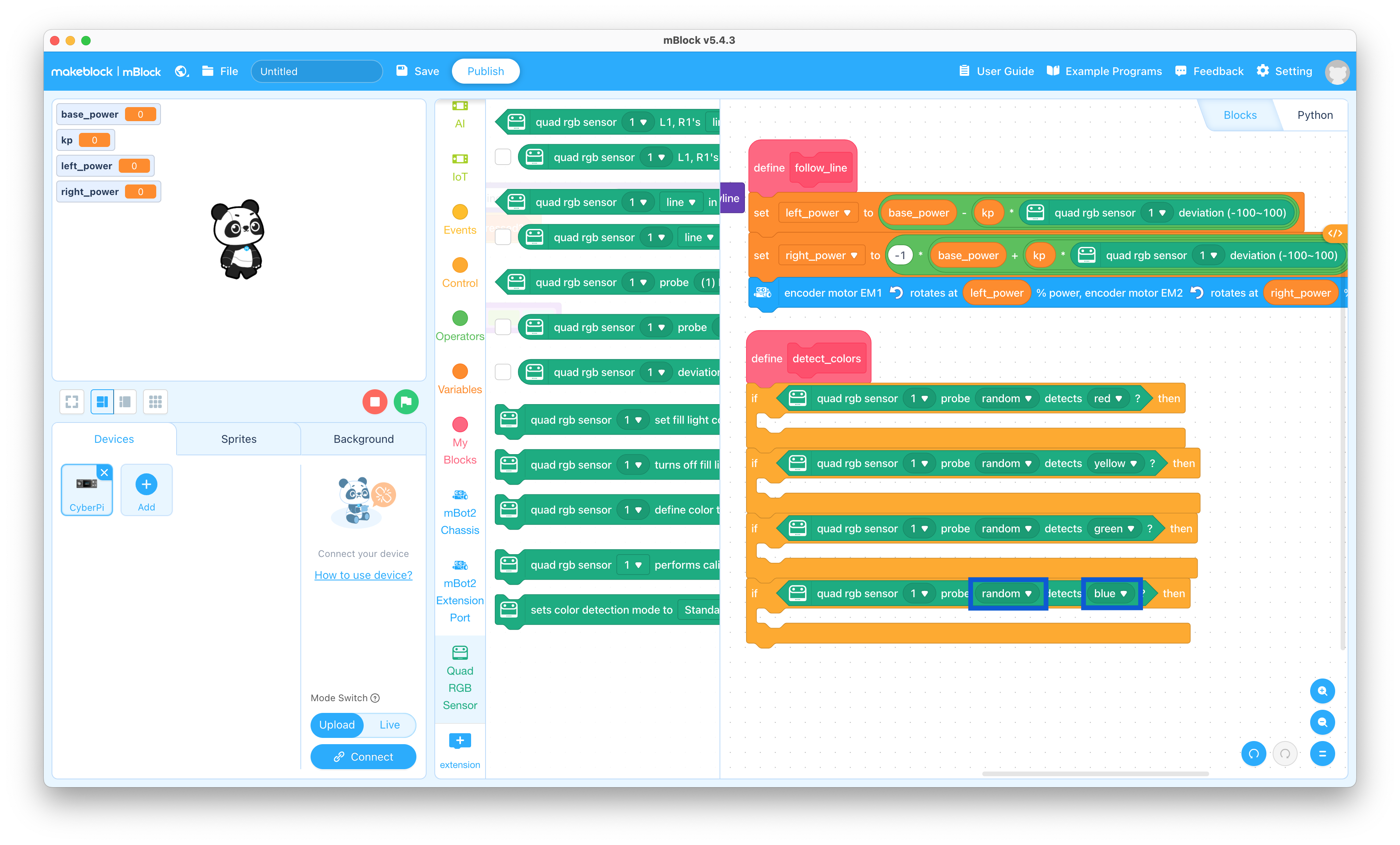
  50. Change the “(1) R2” to “random” and the “line” to “blue” in the bottom “quad rgb sensor 1 probe (1) R2 detects line?” block

    Detect blue line

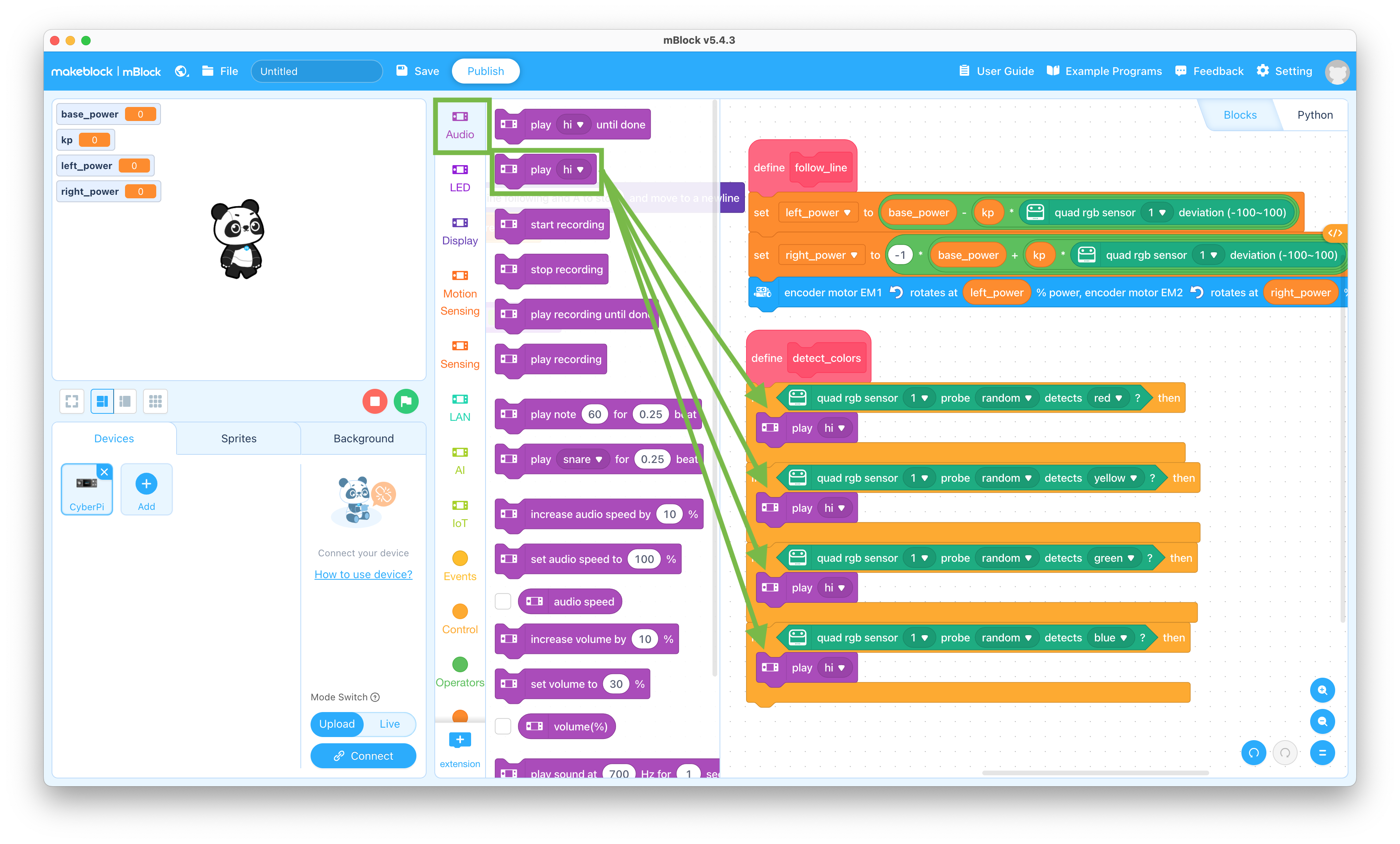
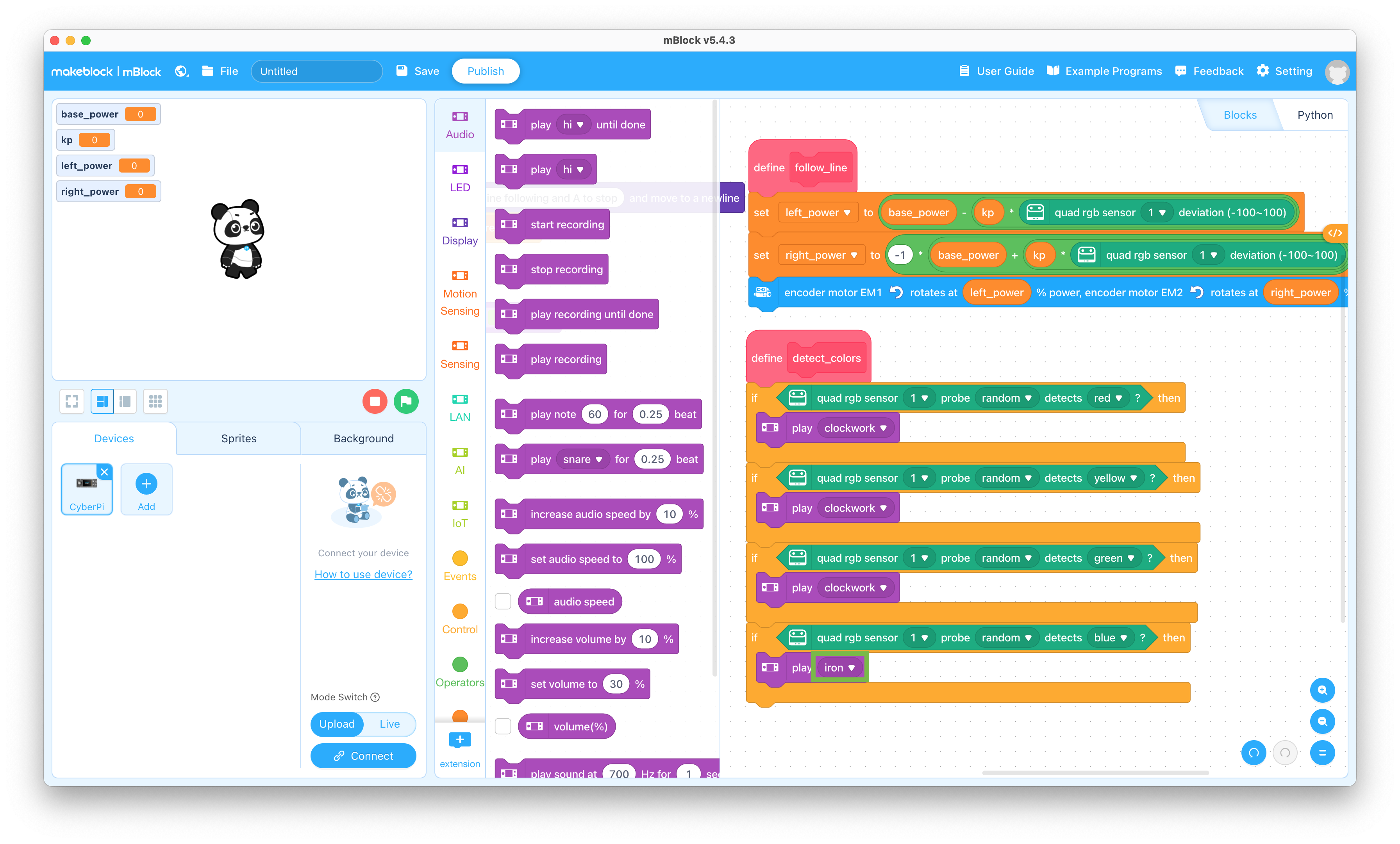
  51. Click the Audio selector and drag the “play hi” block to the coding pane and snap it into each of the if - then blocks

    Play sound block

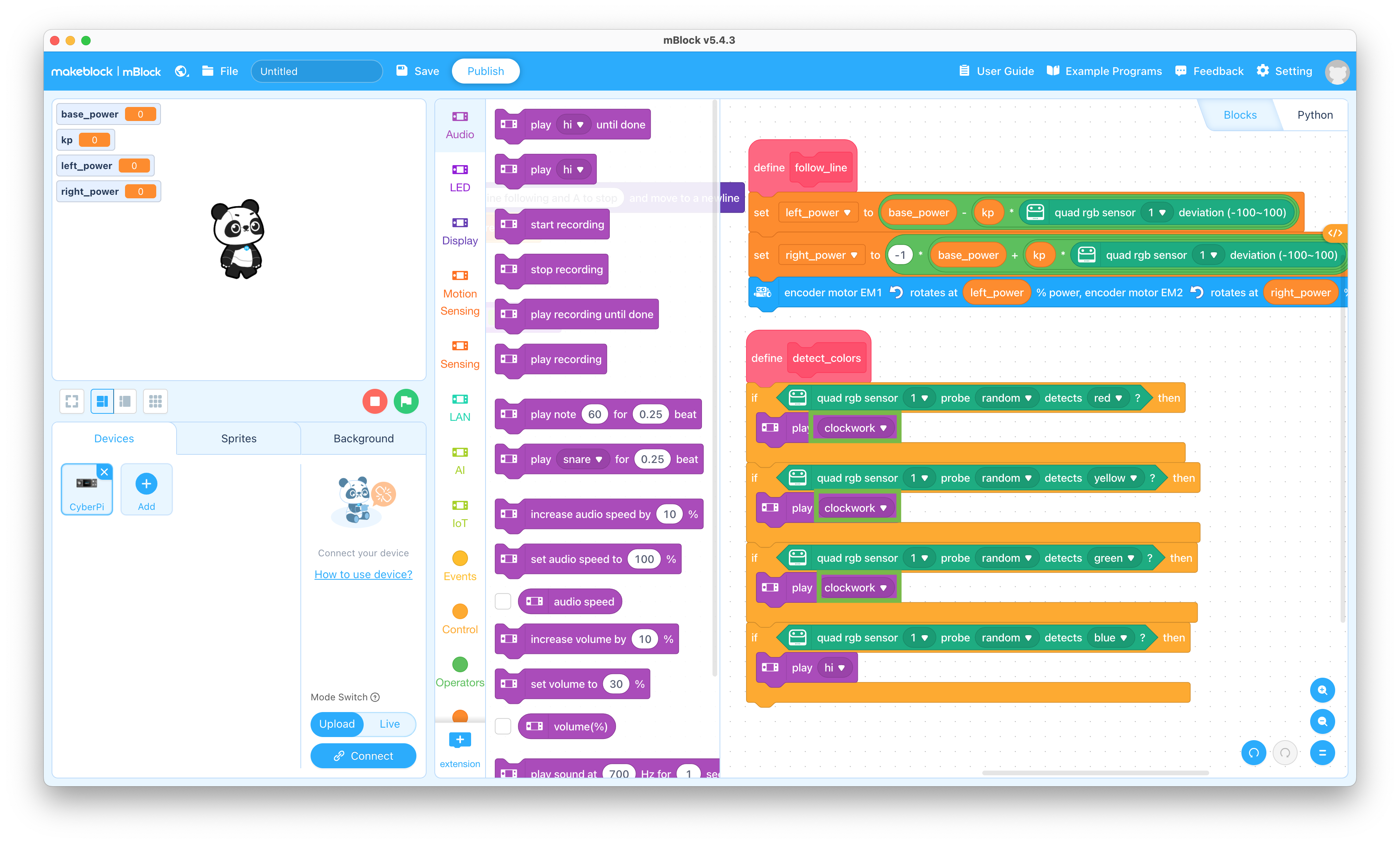
  52. Change the “hi” to “clockwork” in the top three “play hi” blocks

    The clockwork sound is near the bottom of the list

    Play clockwork

  53. Change the “hi” to “iron” in the bottom “play hi” block

    The iron sound is near the bottom of the list

    Play iron

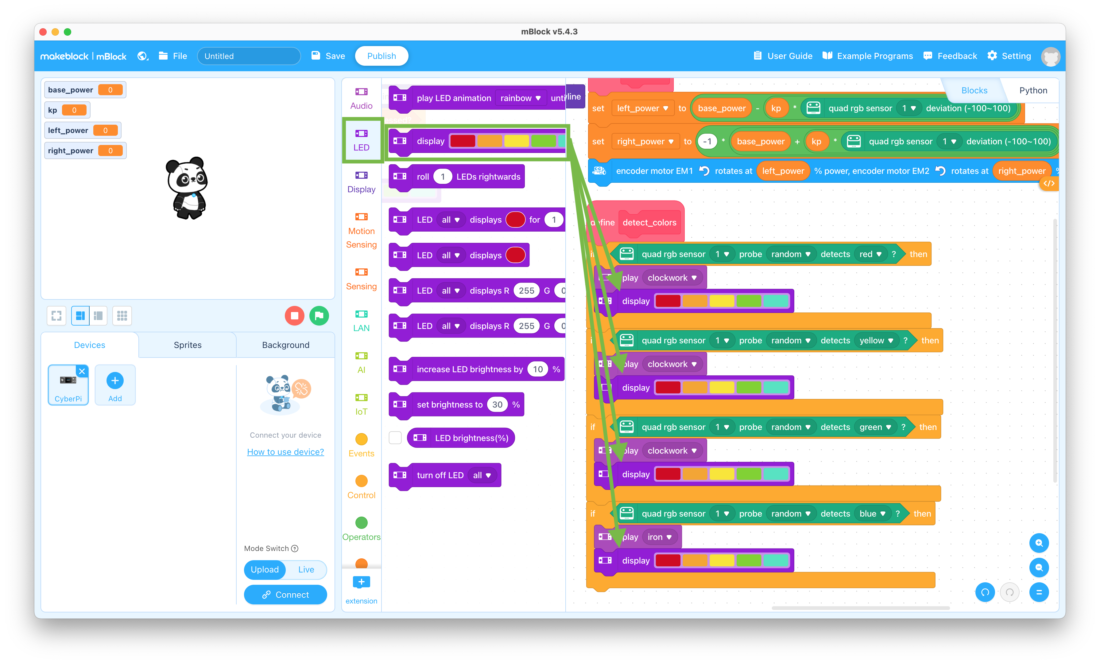
  54. Click the LED selector and drag the “display” block to the coding pane and snap it into each of the if - then blocks

    LED block

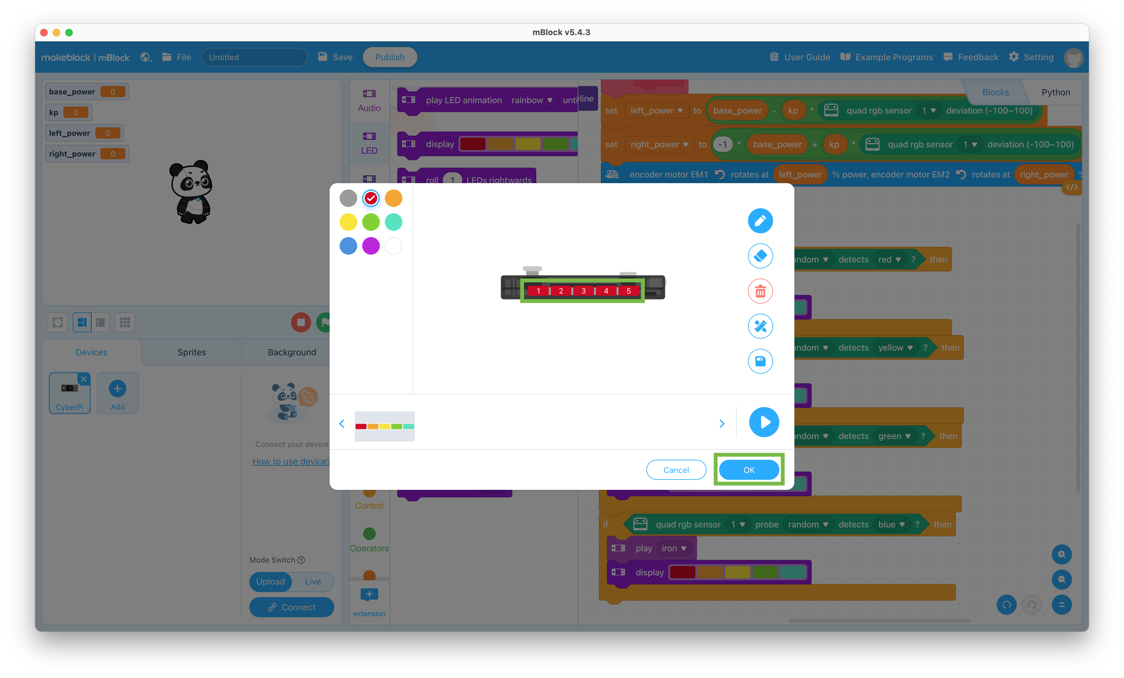
  55. Click on the LED colors in the top display block and change them all to “red”

    Display red

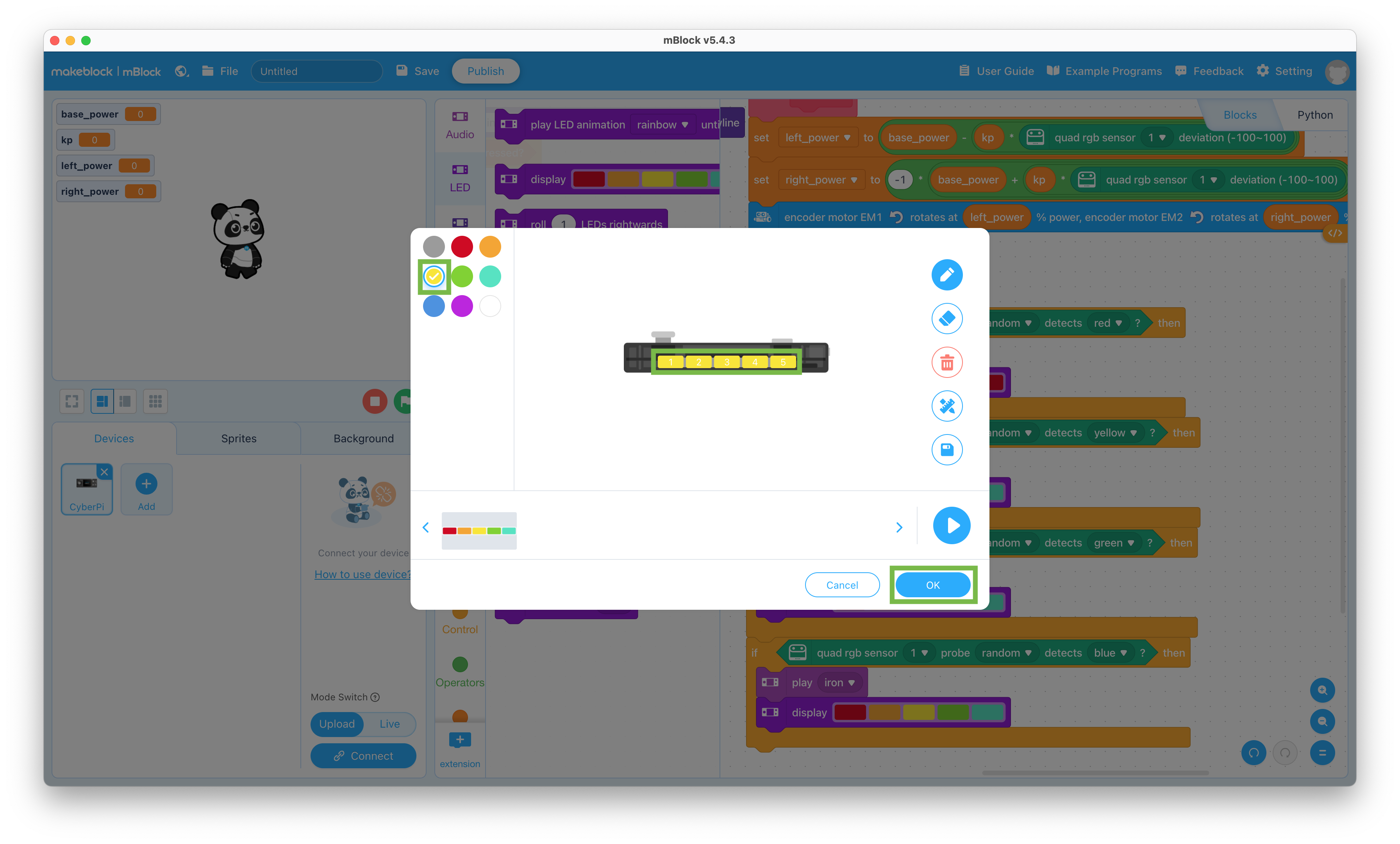
  56. Click on the LED colors in the second display block and change them all to “yellow”

    Display yellow

  57. Click on the LED colors in the third display block and change them all to “green”

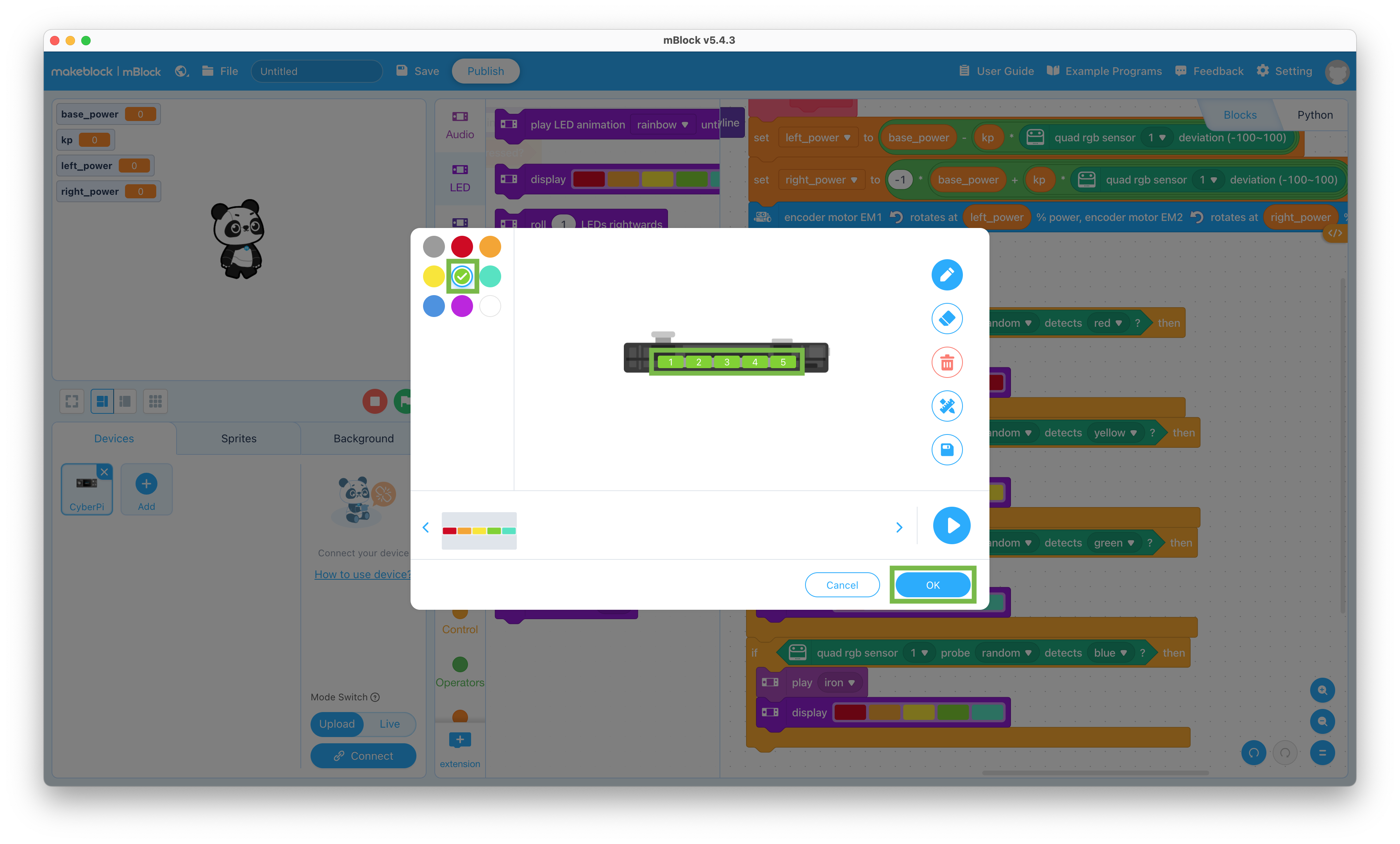
    Display green

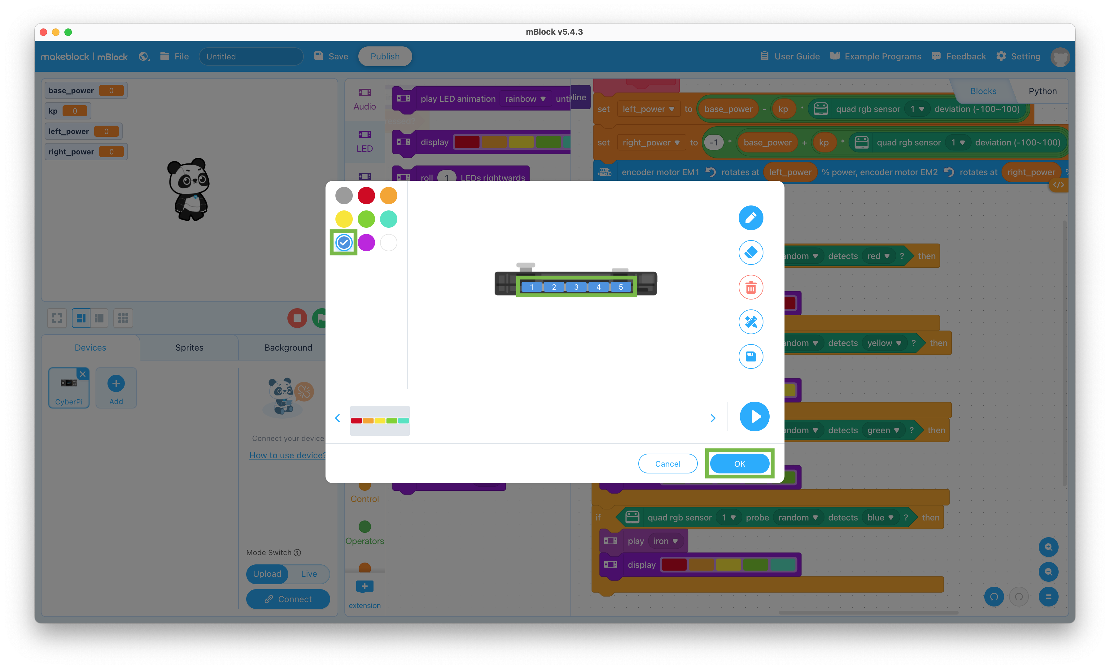
  58. Click on the LED colors in the bottom display block and change them all to “blue”

    Display blue

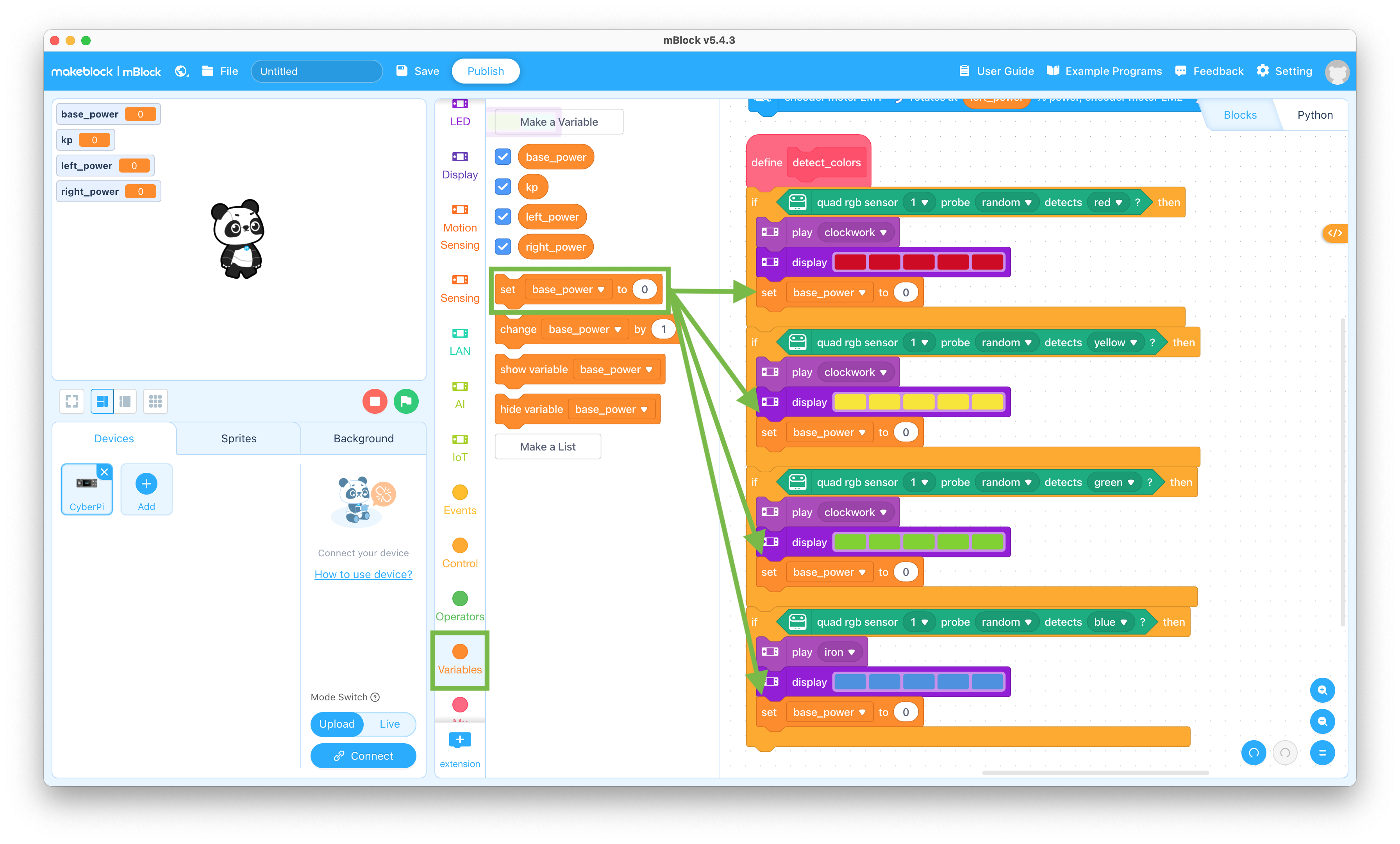
  59. Click the Variables selector and drag the “set base_power to 0” block to the coding pane and snap it into each of the if - then blocks

    Set variable block

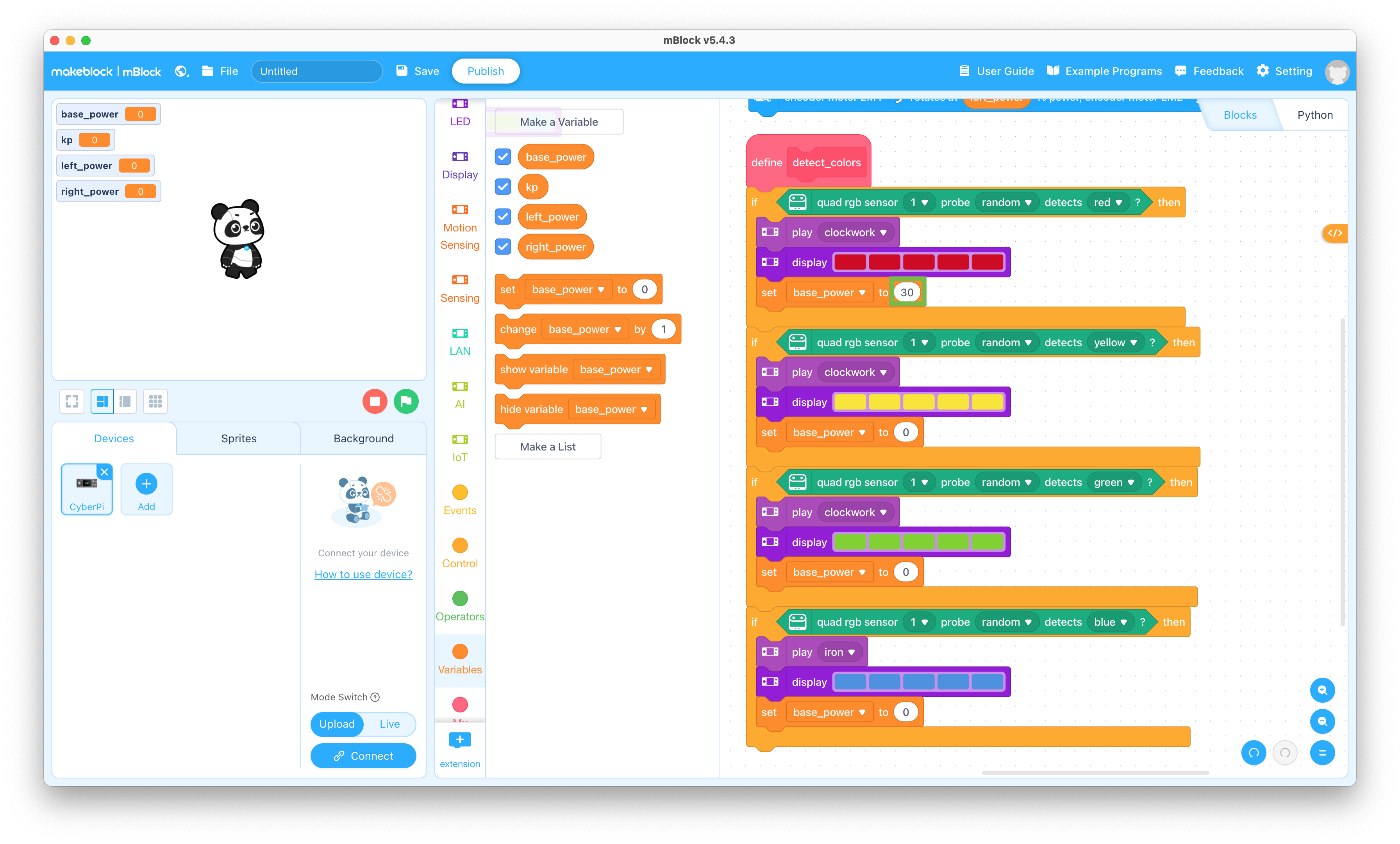
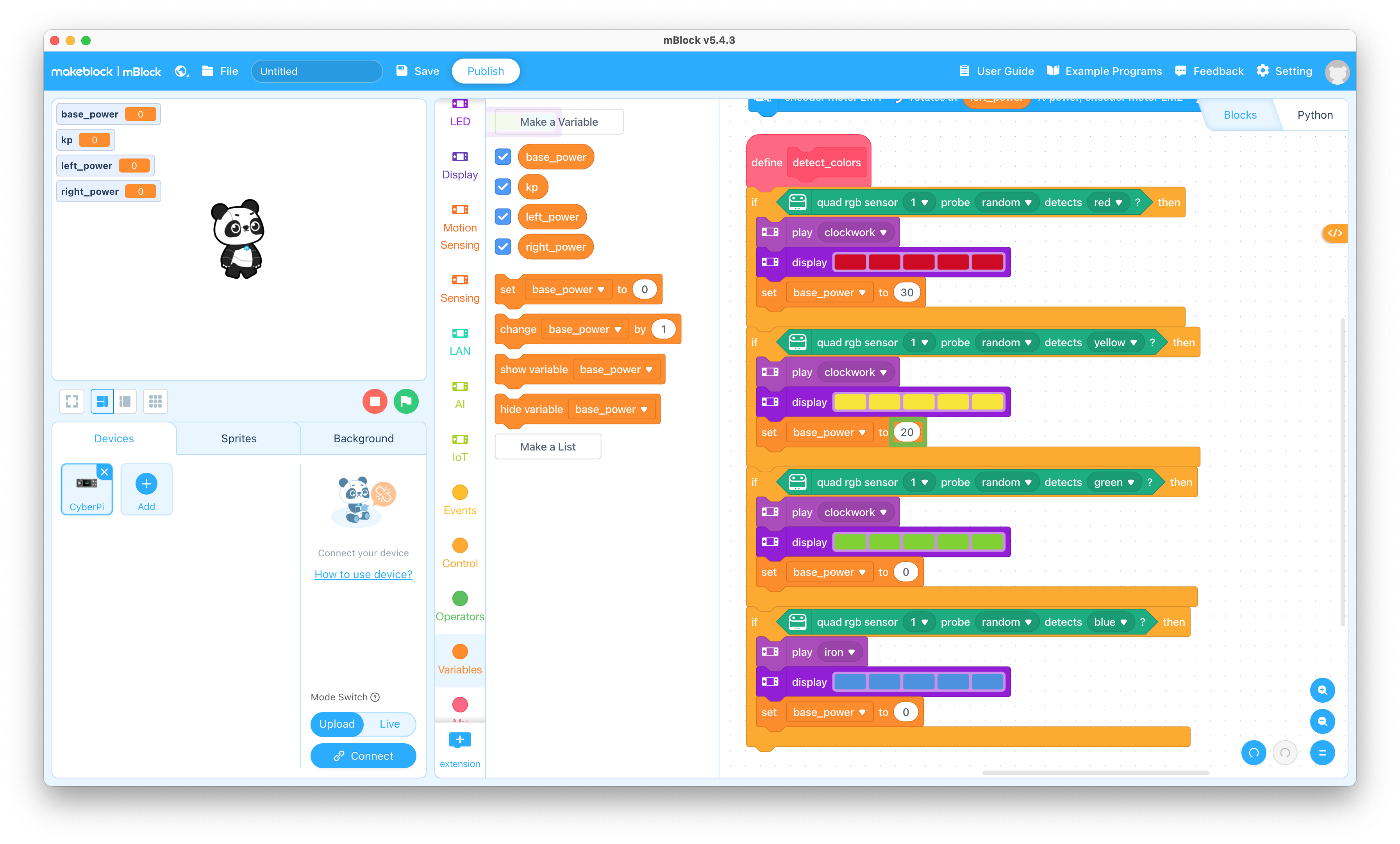
  60. Change the “0” to “30” in the top “set base_power to 0” block

    Set base_power

  61. Change the “0” to “20” in the second “set base_power to 0” block

    Set base_power

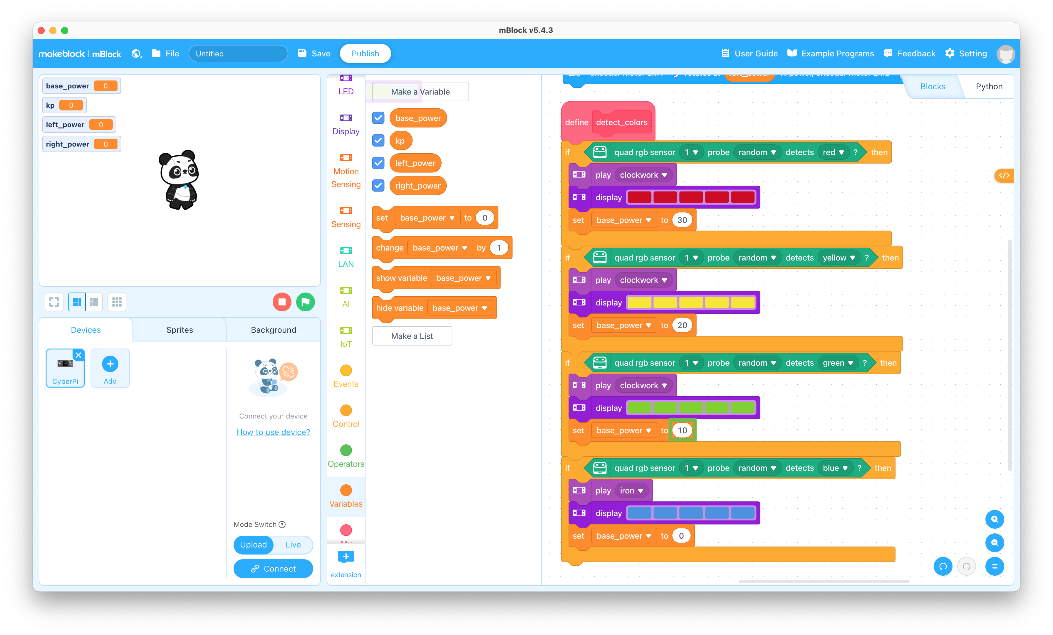
  62. Change the “0” to “10” in the third “set base_power to 0” block

    Set base_power

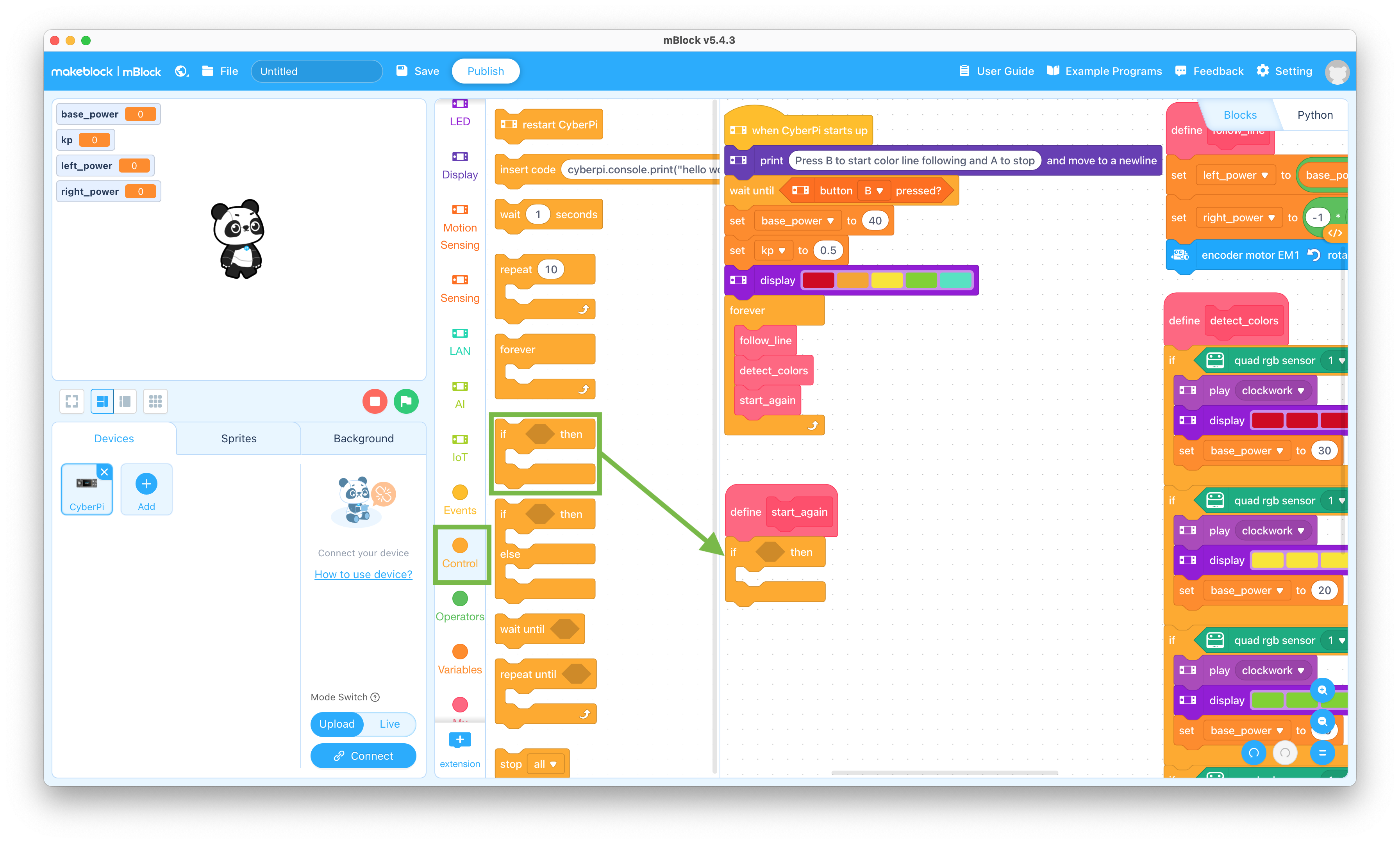
  63. Click the Control selector and drag the “if < > then” block to the coding pane and snap it to the bottom of the Define start_again block

    If-then block

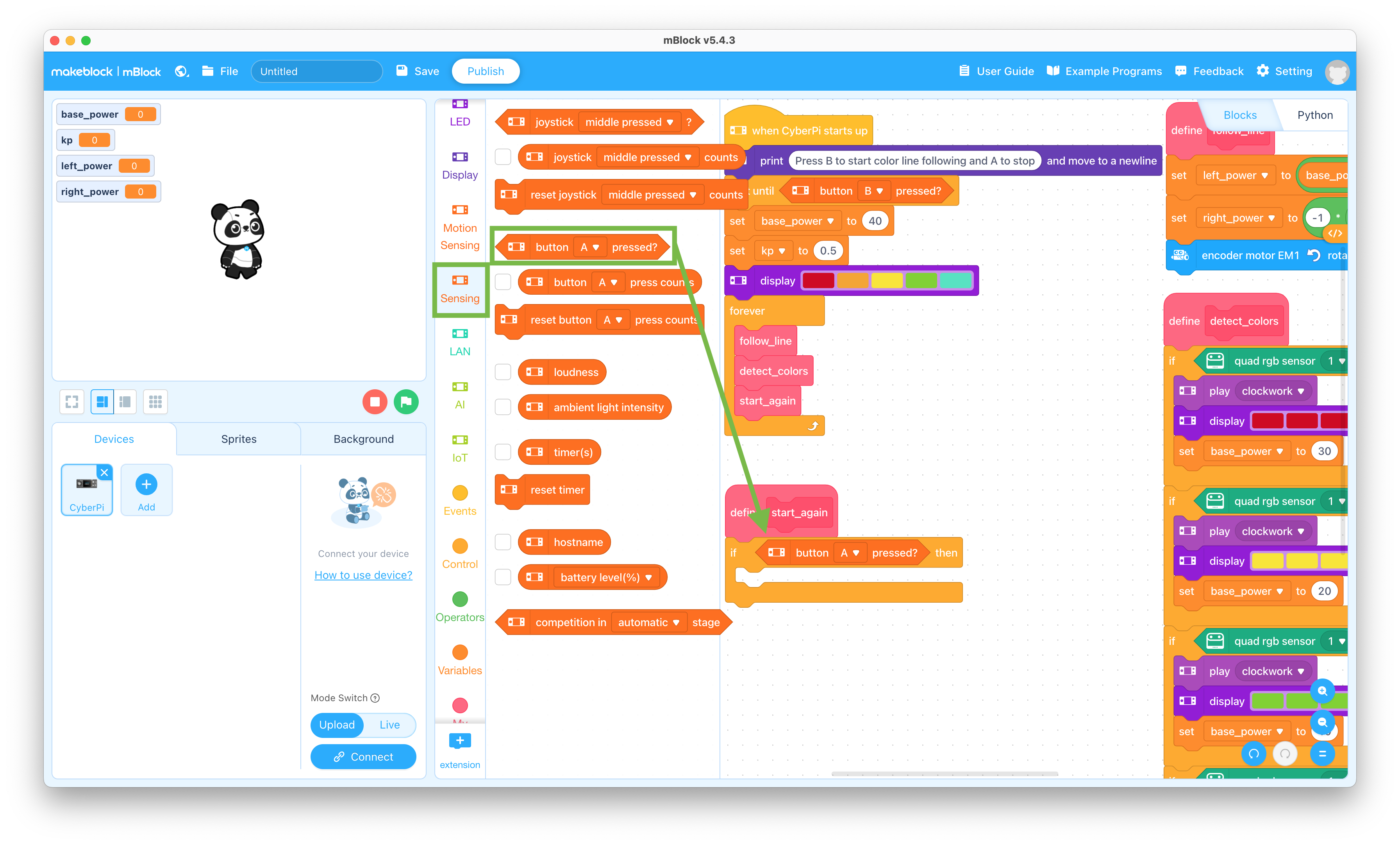
  64. Click the Sensing selector and drag the “button A pressed?” block to the coding pane and snap it into the “if < > then” block

    This allows you to start the mBot Neo line following again after it stops

    Button A pressed block

  65. Change the “A” to “B” in the “if button A pressed then” block

    Set B button

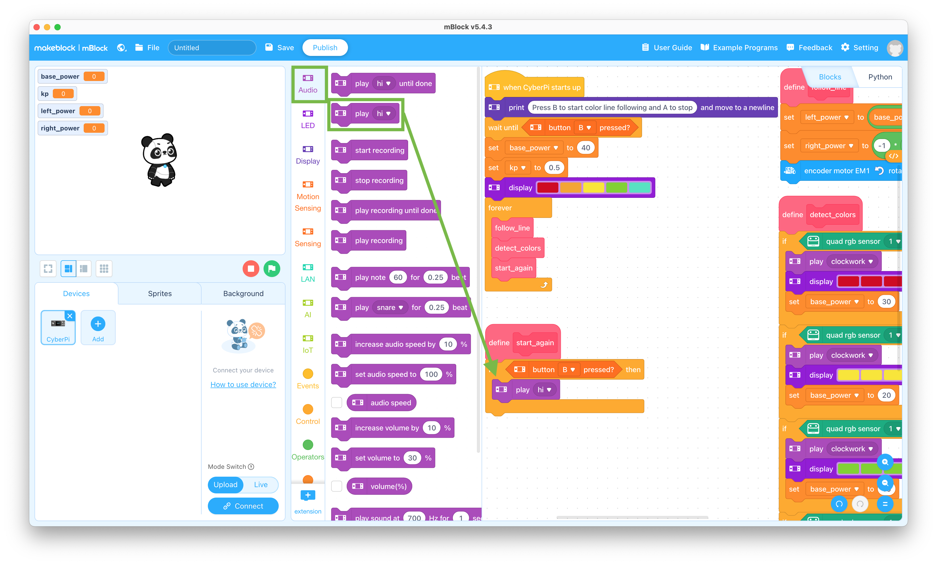
  66. Click the Audio selector and drag the “play hi” block to the coding pane and snap it into the if - then block

    Play sound block

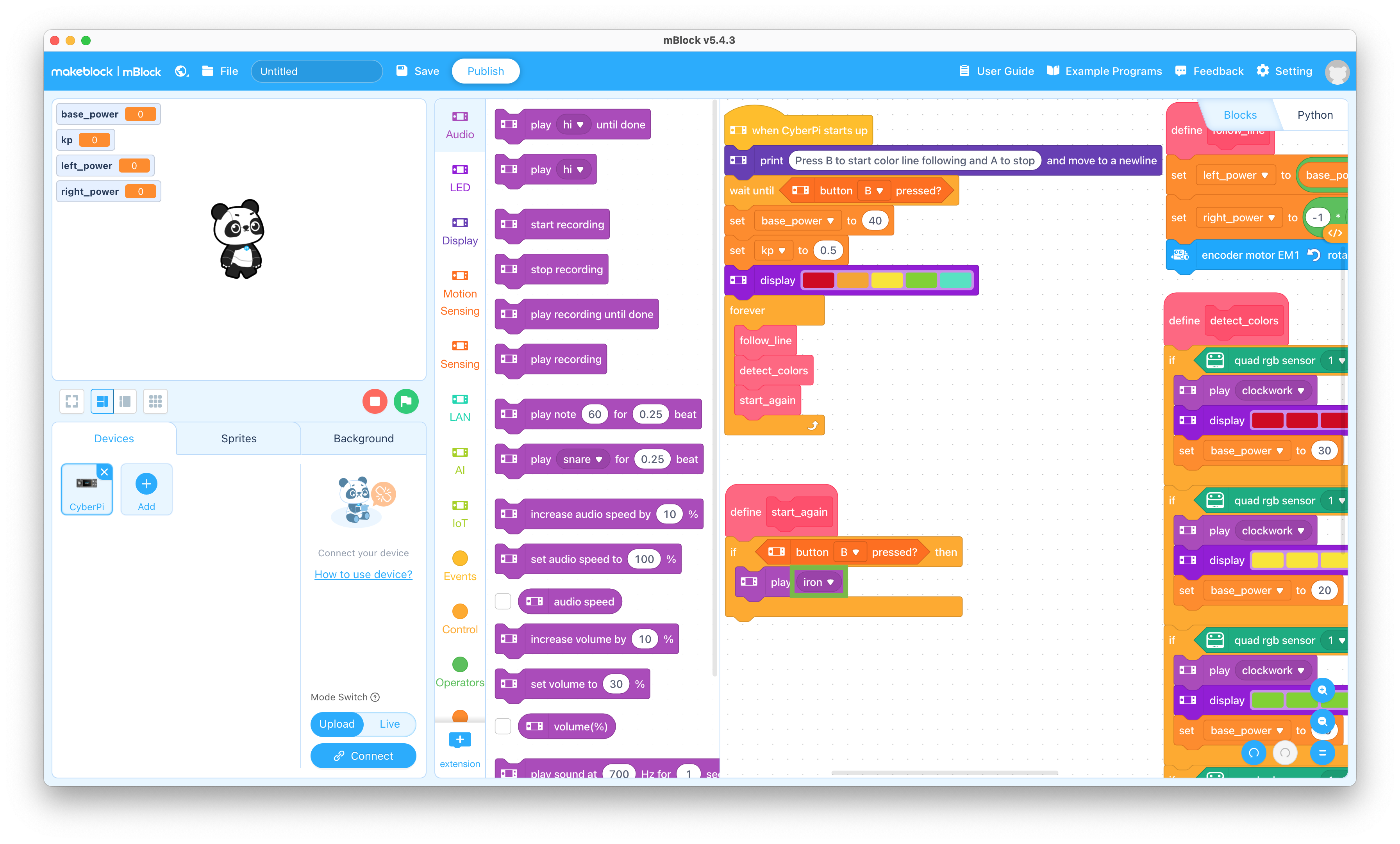
  67. Change the “hi” to “iron” in the “play hi” block

    The iron sound is near the bottom of the list

    Play iron

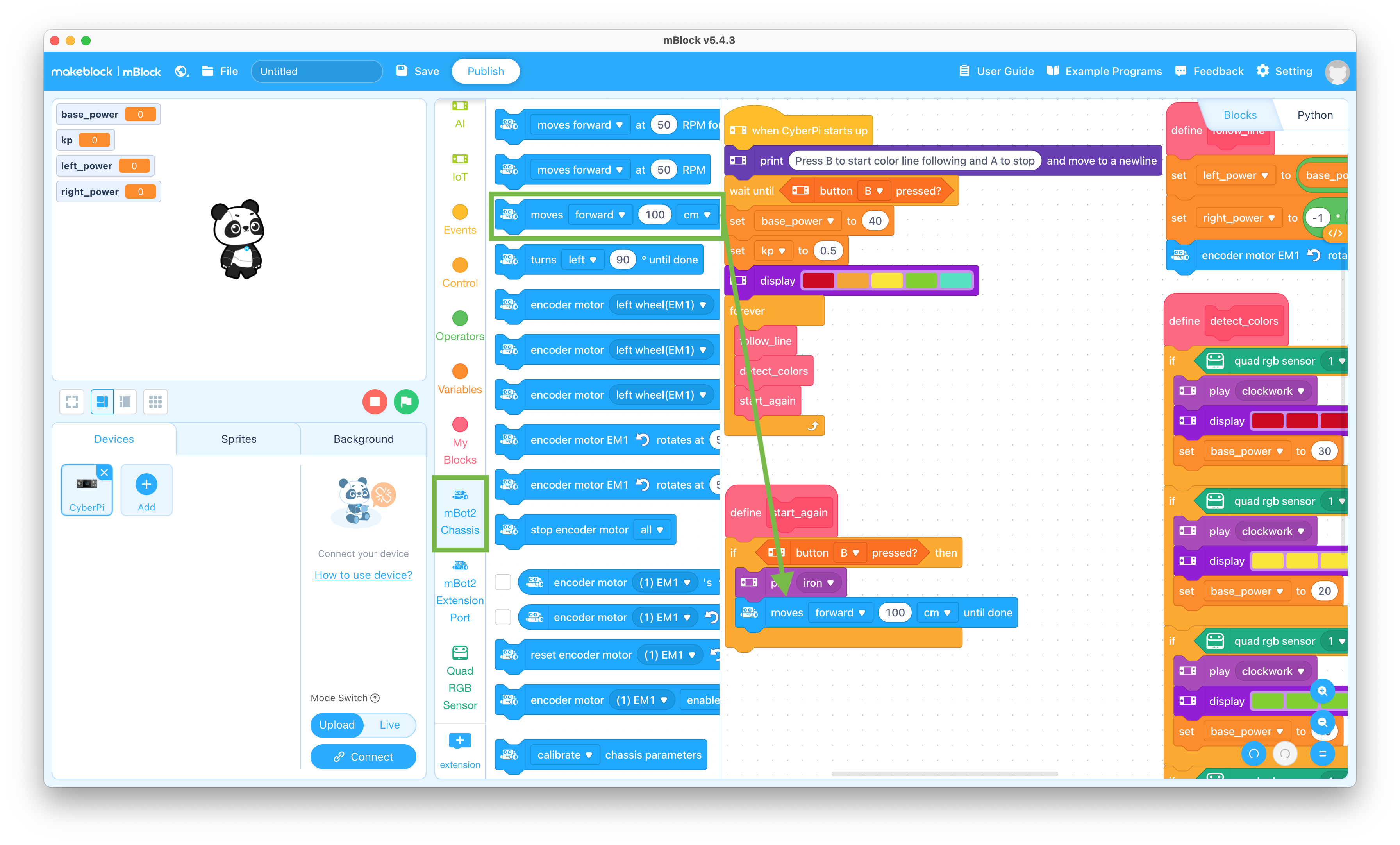
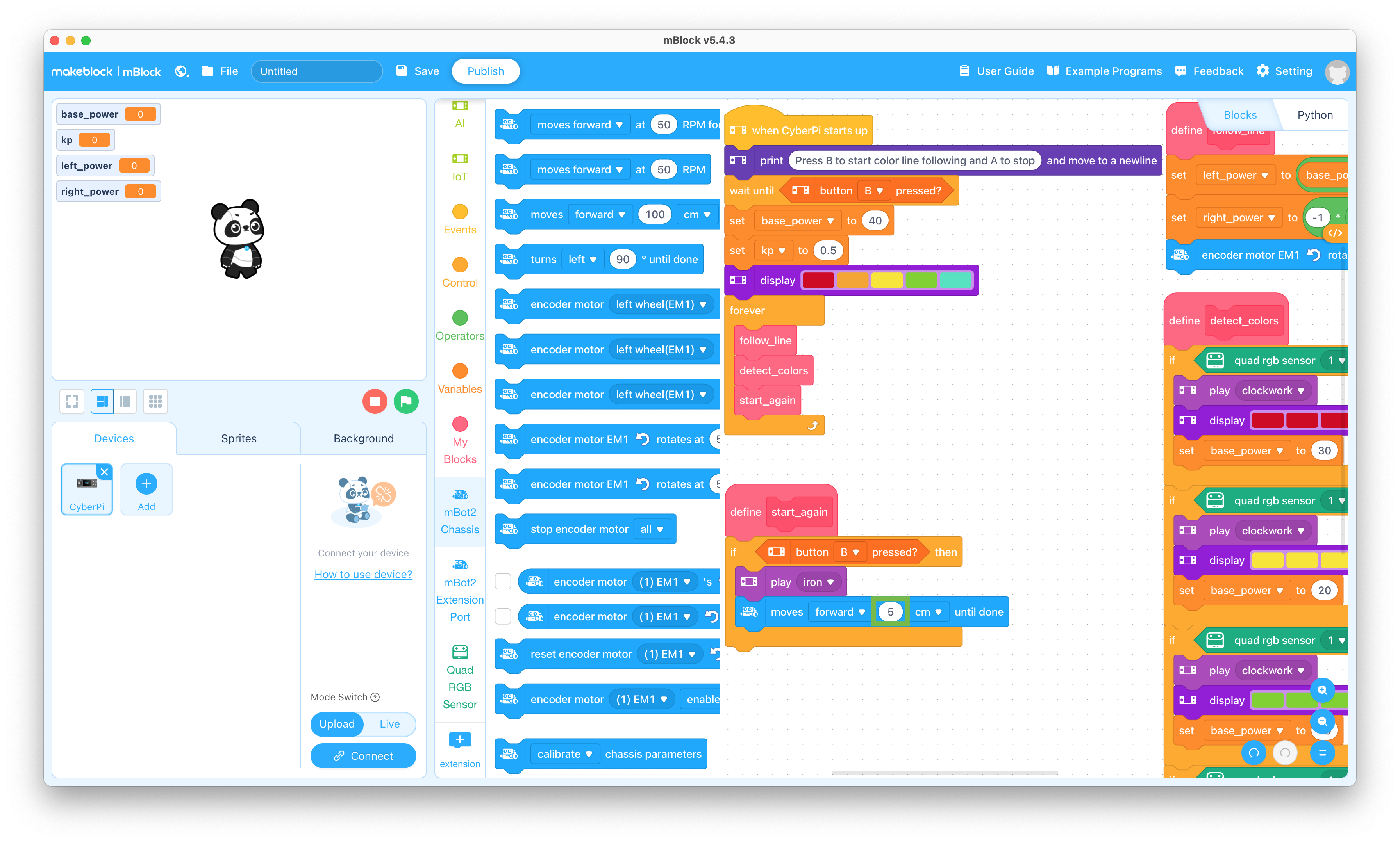
  68. Click the mBot2 Chassis selector and drag the “moves forward 100 cm until done” block to the coding pane and snap it into the if - then block

    Move forward block

  69. Change the “100” to “5” in the “moves forward 100 cm until done” block

    Move 5 cm

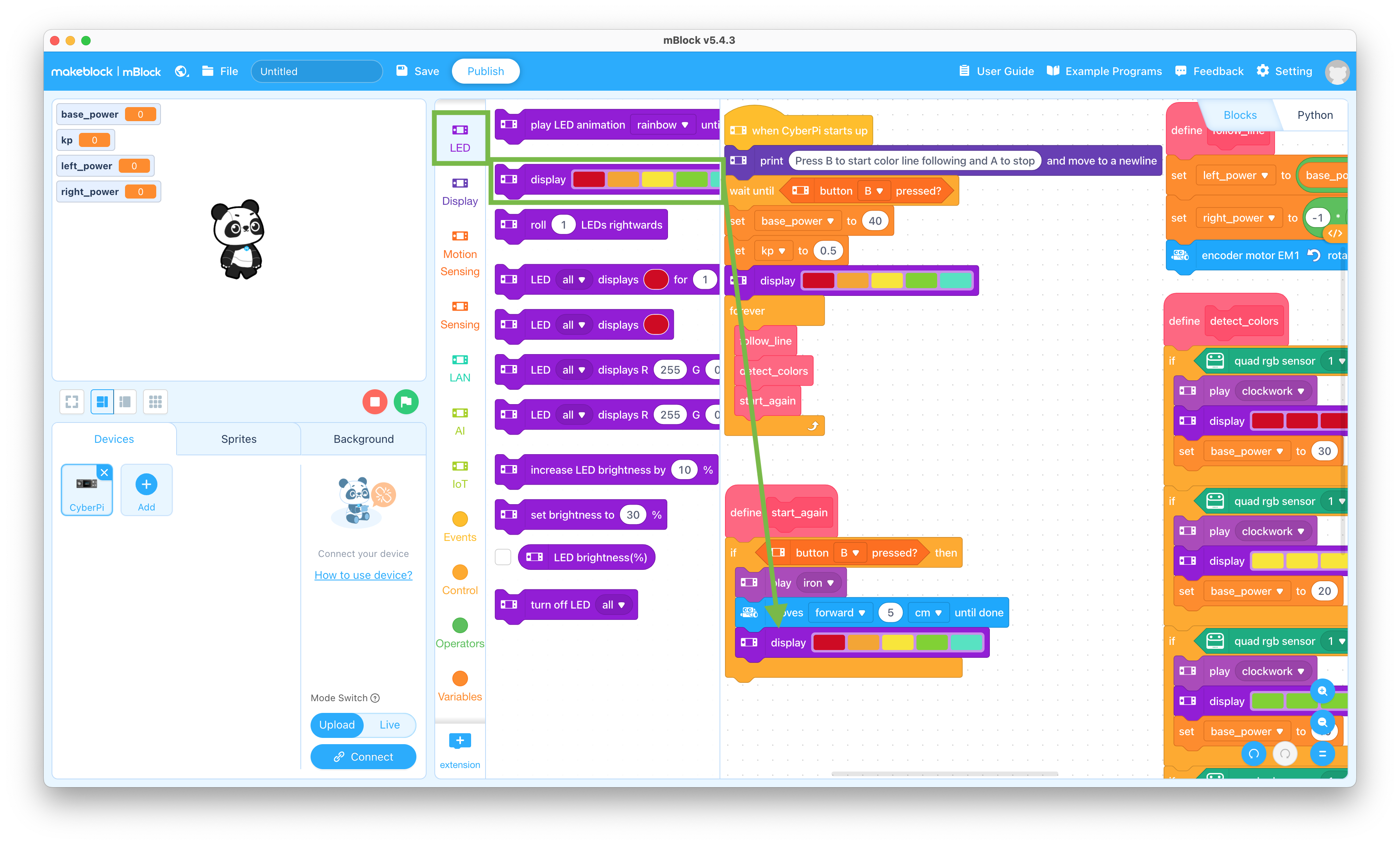
  70. Click the LED selector and drag the “display” block to the coding pane and snap it into the if - then block

    LED block

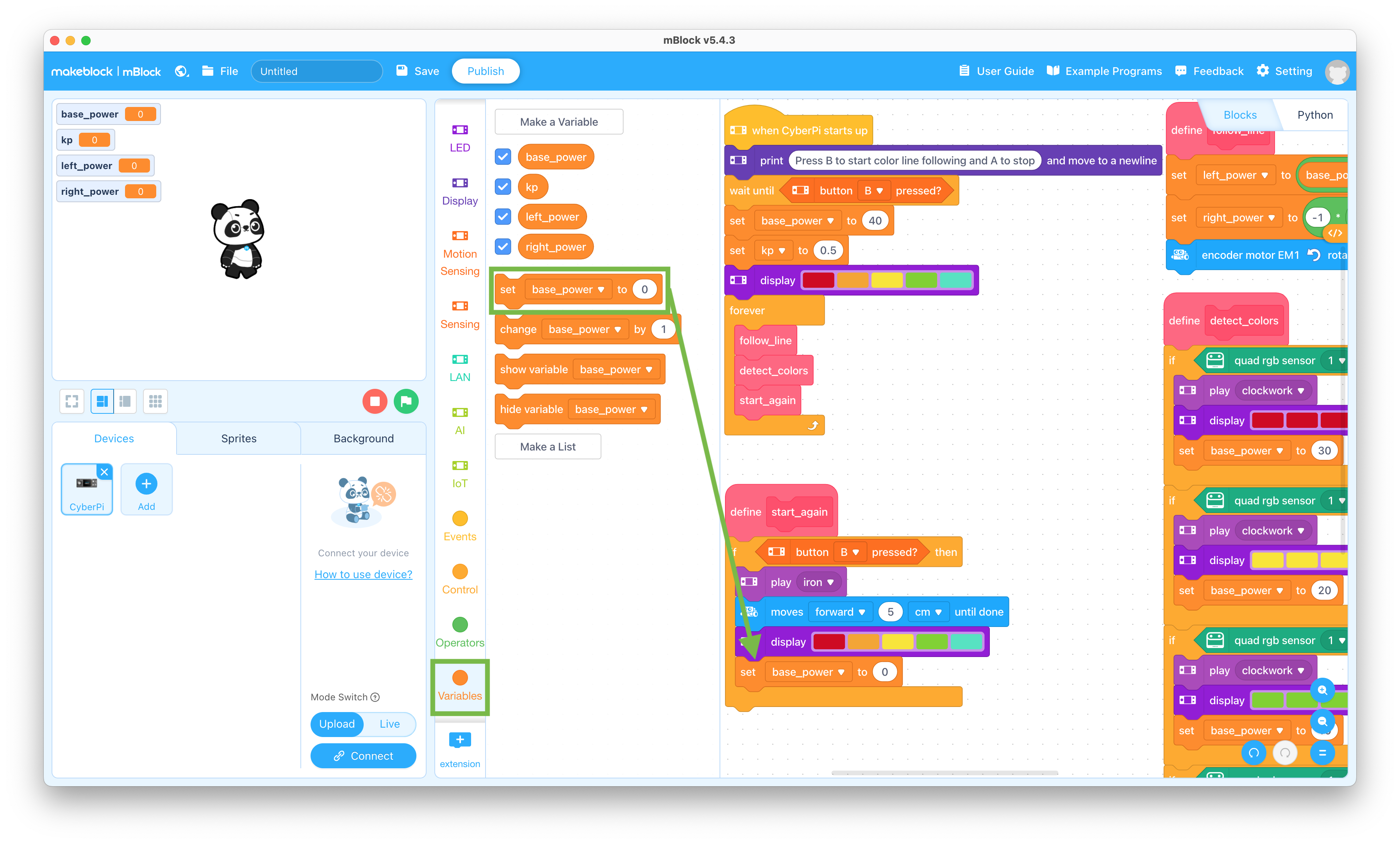
  71. Click the Variables selector and drag the “set base_power to 0” block to the coding pane and snap it into the if - then block

    Set variable block

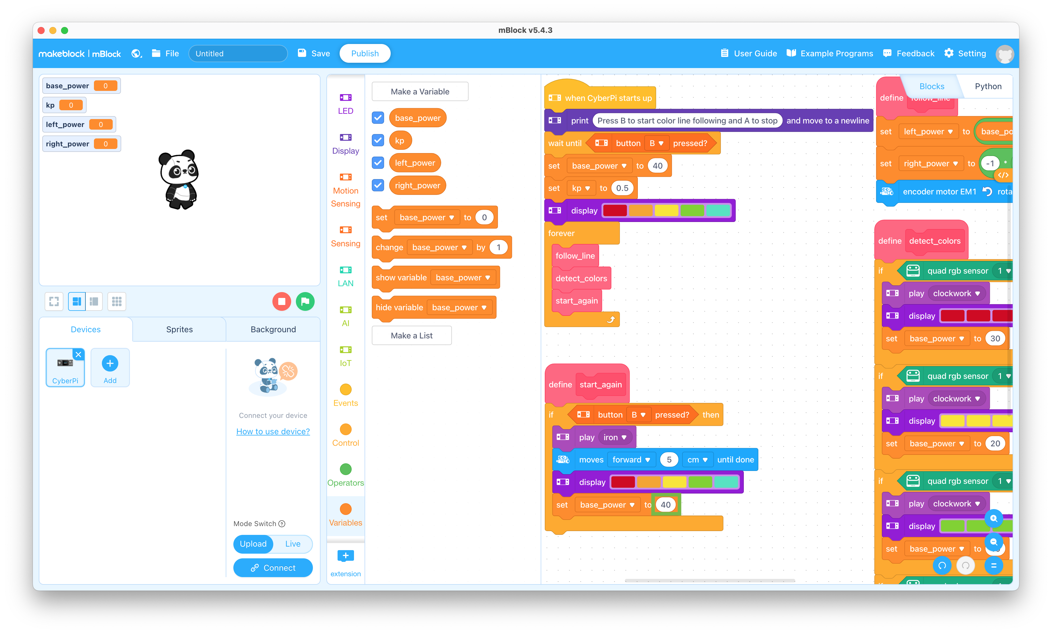
  72. Change the “0” to “40” in the “set base_power to 0” block

    Set base_power

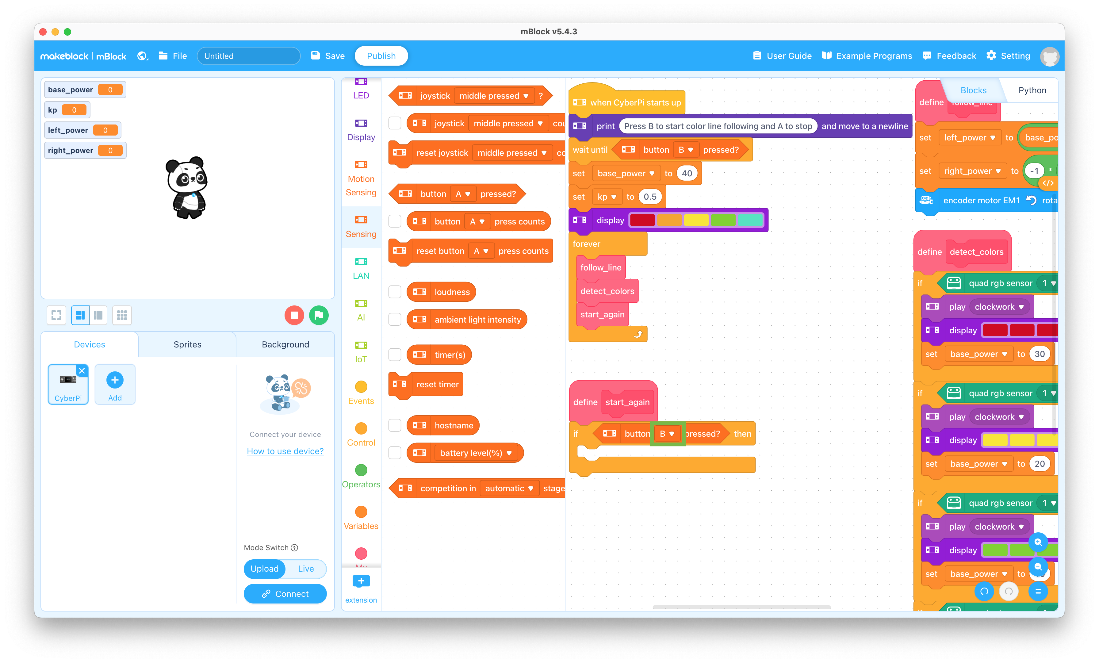
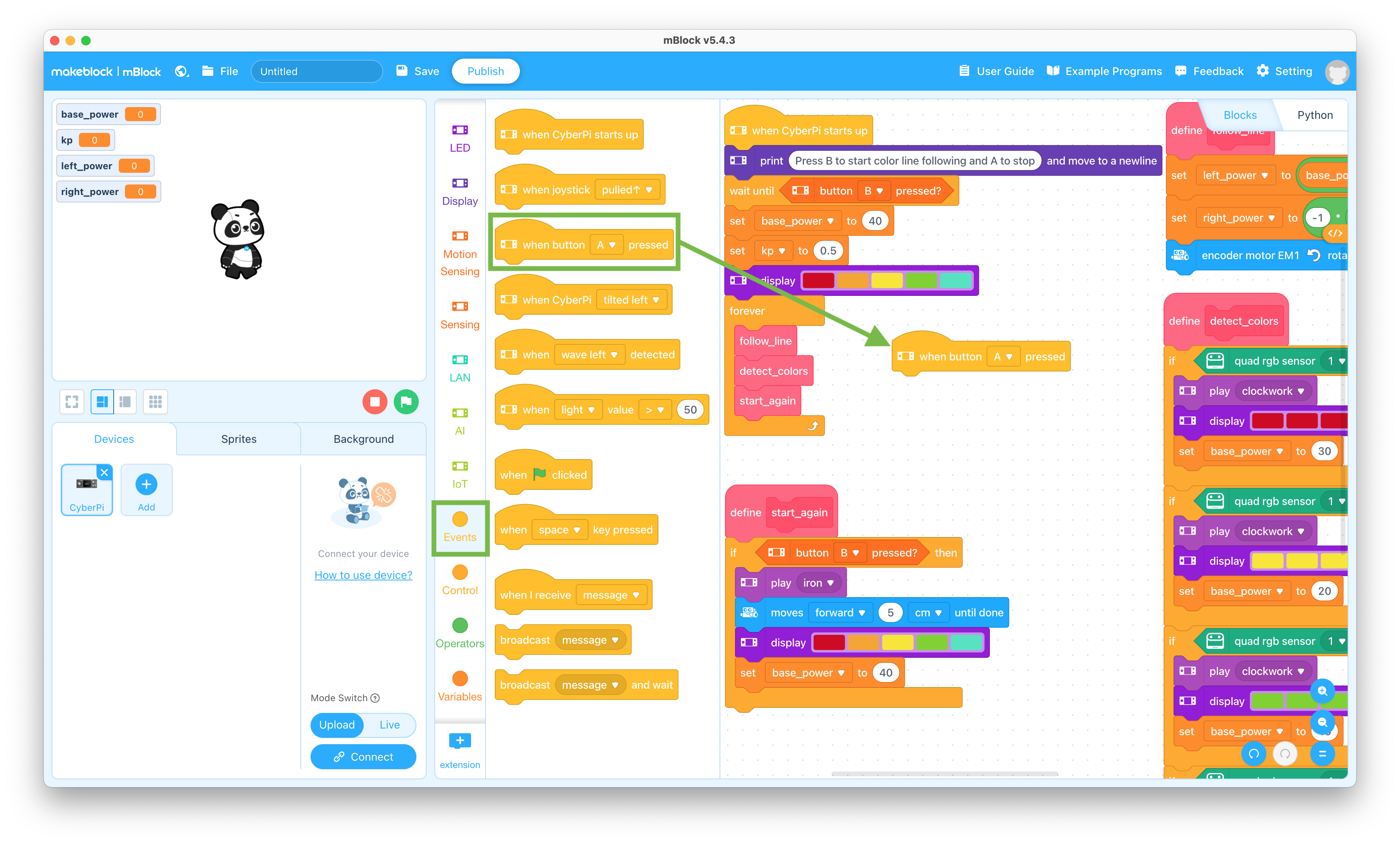
  73. Click the Events selector and drag the “when button A pressed” block to an empty area of the coding pane

    Button pressed event block

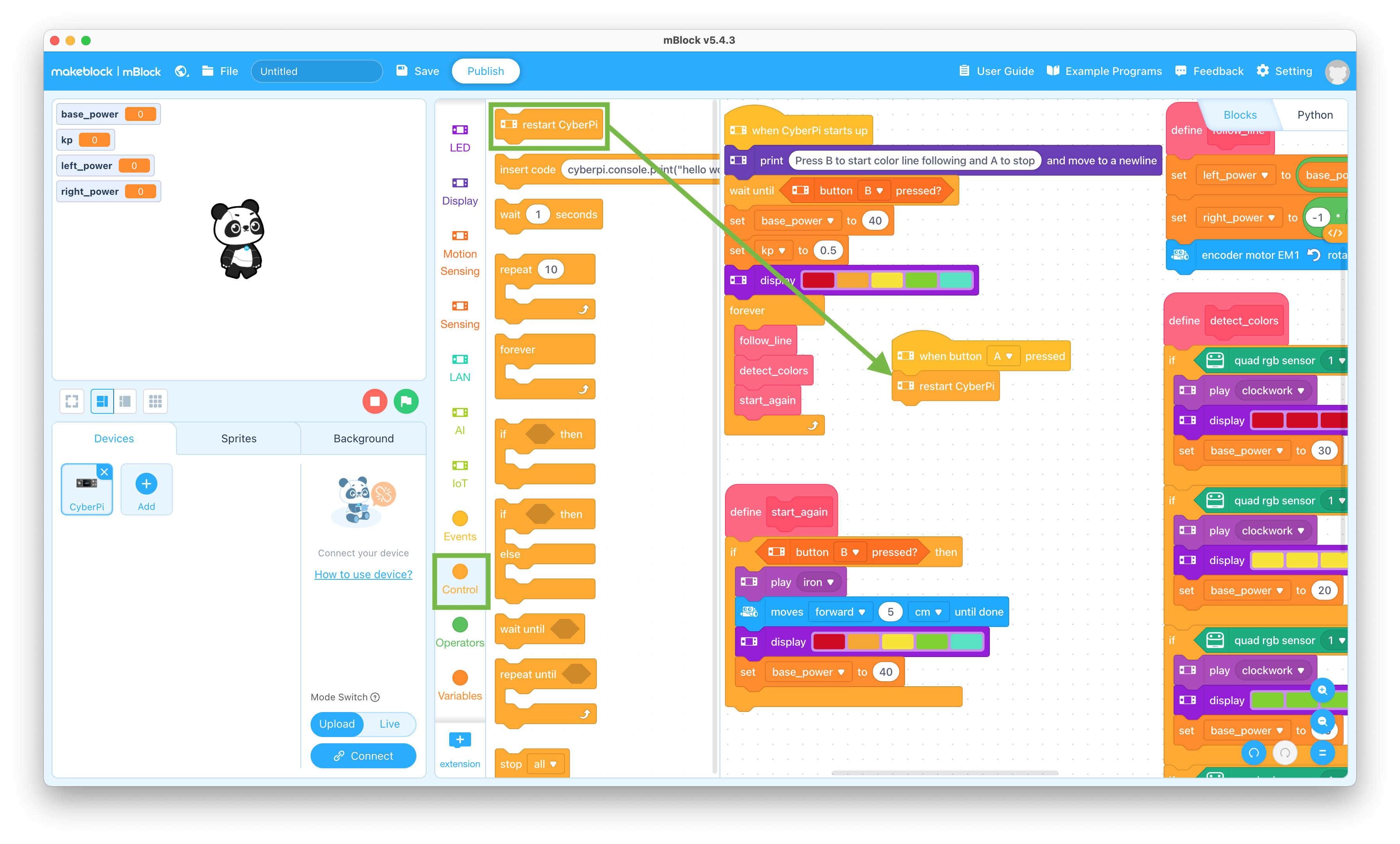
  74. Click the Control selector and drag the “restart CyberPi” block to the coding pane and snap it to the bottom of the when button A pressed block

    This will cause the mBot Neo to restart things when when the A button is pressed no matter what is happening in the forever loop

    Restart CyberPi block

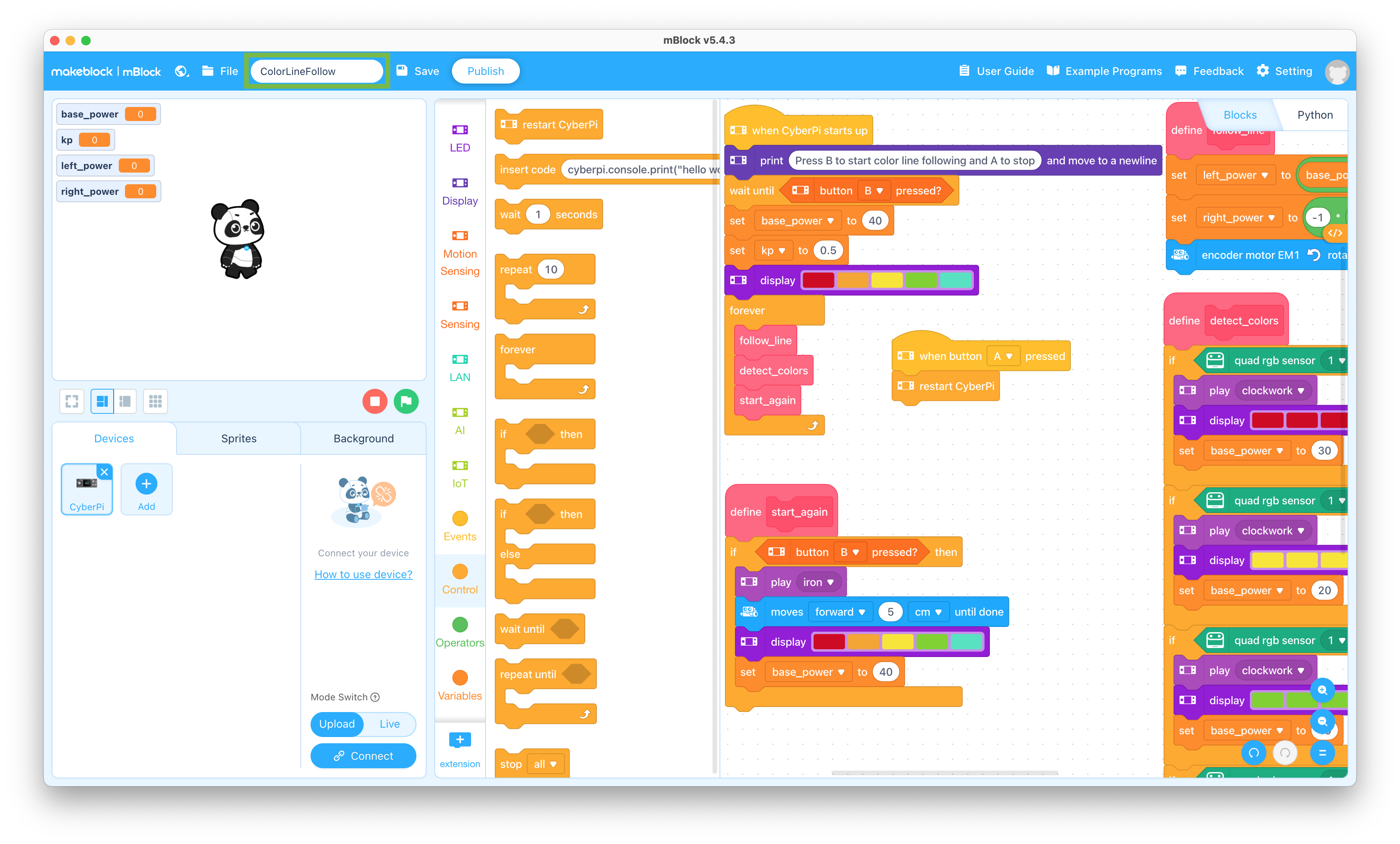
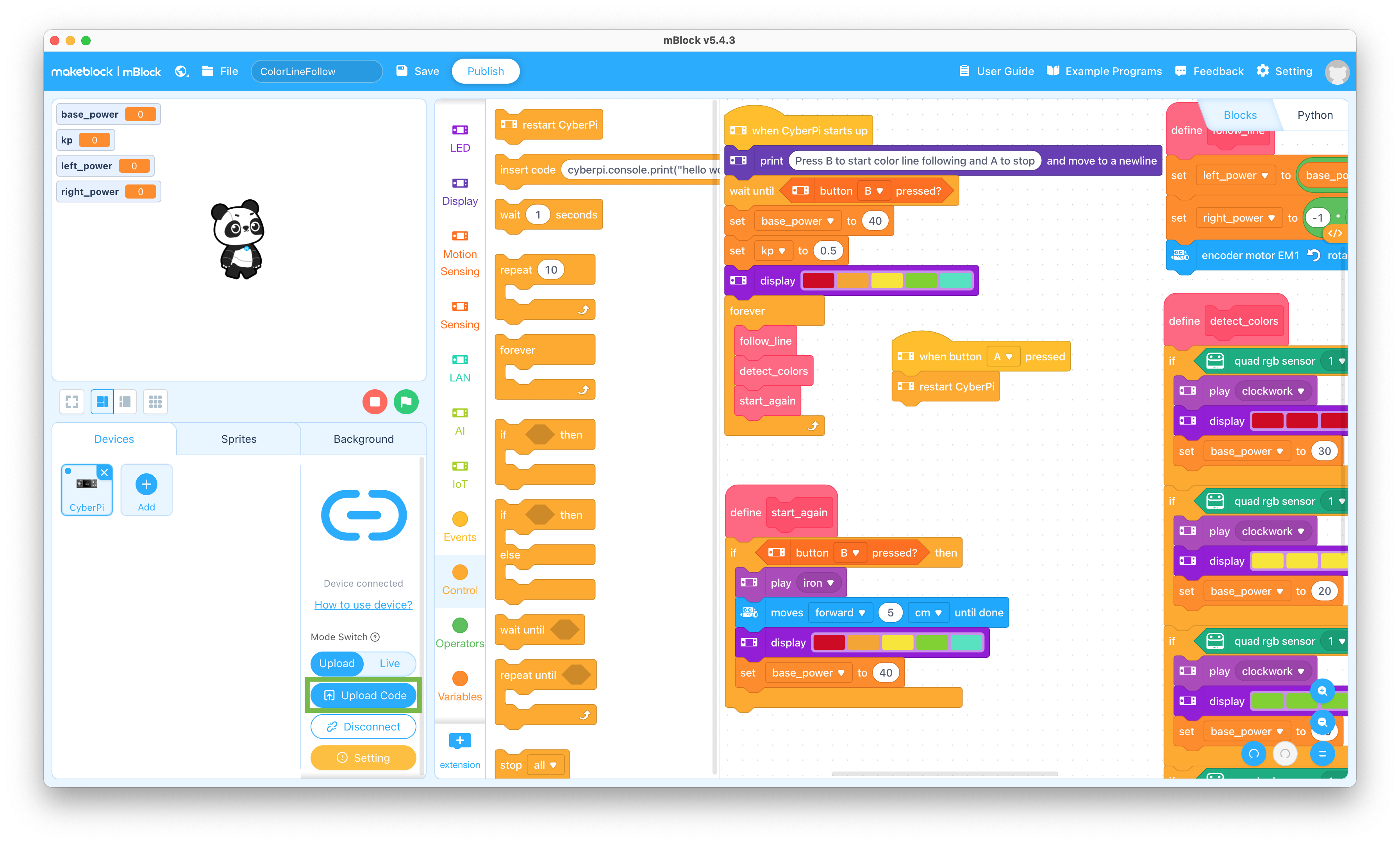
  75. Change the name of the program in the upper left to “ColorLineFollow”

    Change Program Name

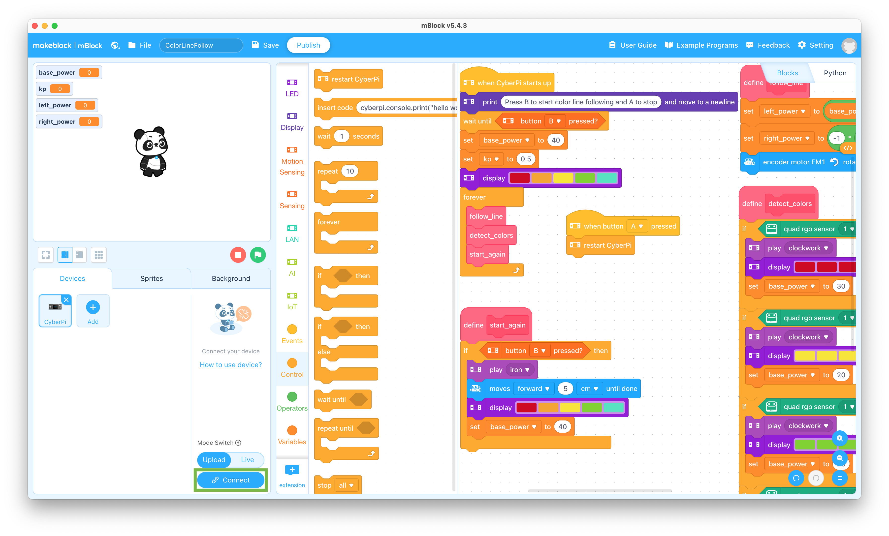
  76. Slide the power switch on the mBot2 Shield to the ON position and click the Connect button

    Connect to CyberPi

  77. Click the Upload Code button and wait for the upload to complete

    Upload program to mBot

  78. Slide the power switch on the mCore mainboard on the mBot to the OFF position and disconnect the USB cable from the mBot Neo

Robot Testing

Follow the steps below to test out the program you just created

  1. Place the line following map on the floor
  2. Place the mBot on the line and slide the power switch on the mBot2 Shield on the mBot Neo to the ON position
  3. Press the B button on the CyberPi to start the mBot Neo moving
  4. When you're finished watching the mBot Neo follow the line, press the A button
  5. Change the sounds and LED colors to see how they change what the mBot Neo does

What is your favorite sound?

Try changing the LED display block with the LED animation block to see what it does

What changes will make the mBot Neo accelerate on detecting colors after it has stopped?

When you're ready to try out changes to your program, connect the USB cable to the CyberPi on the mBot Neo, plug the cable into your computer, and repeat steps 76 through 78 above

Return to Main mBot Neo page

"Whatever you do, work heartily, as for the Lord and not for men, knowing that from the Lord you will receive the inheritance as your reward. You are serving the Lord Christ. - Colossians 3:23-24"
mbotneo/lesson5.txt · Last modified: 2024/03/29 11:52 by jstruebel