Table of Contents
Objective
This first lesson will show you how to assemble the PiBot. It will then show you how to configure and use the Raspberry Pi to control the PiBot with a simple Python program. Finally it will describe how the electronics work together to control the PiBot.
Parts Required
The parts below are required to complete this lesson. Note that all parts except the Raspberry Pi board and optional hardware are included in the OSOYOO kit that can be purchased on Amazon.
- Raspberry Pi 4 or 3B board
- OSOYOO Top & Bottom Chassis Plates
- OSOYOO Motors and wheel x2
- OSOYOO universal wheel
- OSOYOO Model Pi motor driver board
- OSOYOO PCA9685 compatible module
- OSOYOO Voltage Meter
- 18650 Battery box
- 18650 batteries x2
- Jumper wires & Hardware
- Optional Hardware
- M2.5x5mm Hex Cap Screws
- M2.5 Plastic Washers
- M2.5x5mm+6mm Hex Brass Pillars
- M2.5 Hex Nuts
Hardware Assembly
When handling any of the circuit boards make sure to wear your ESD wrist strap and have it connected to an earth ground point
When installing items with multiple screws or nuts, leave them loose until all are installed and then tighten to ensure that you can get them all inserted
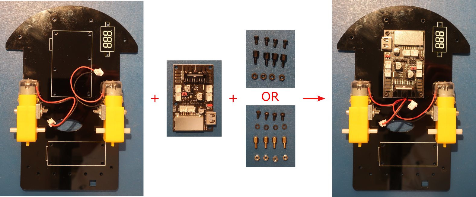
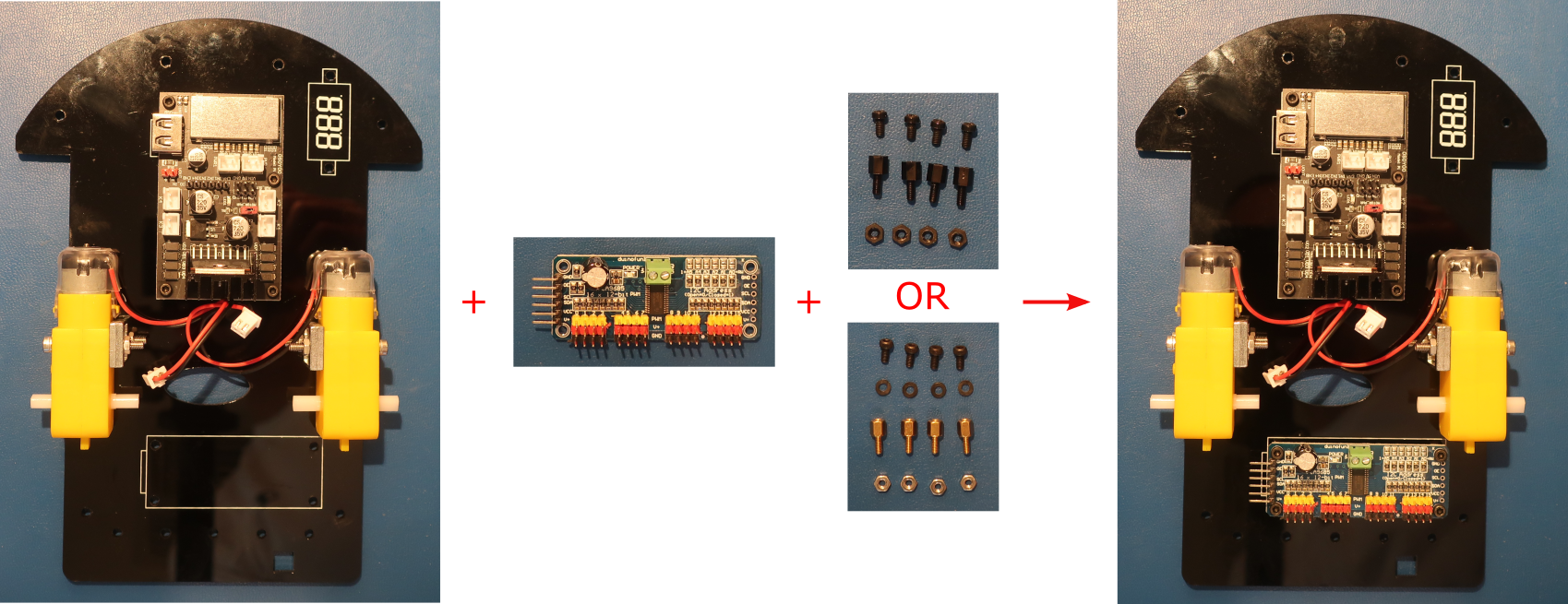
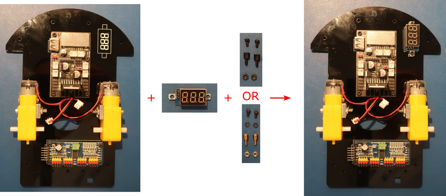
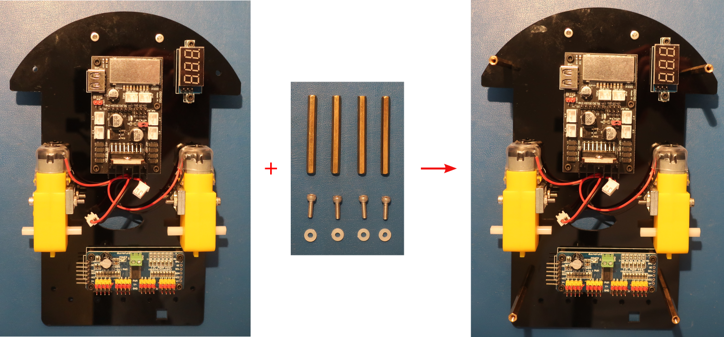
When installing a board using the M2.5x5mm+6mm pillars, attach the pillars to the board with the screws and then install on the chassis with the nuts
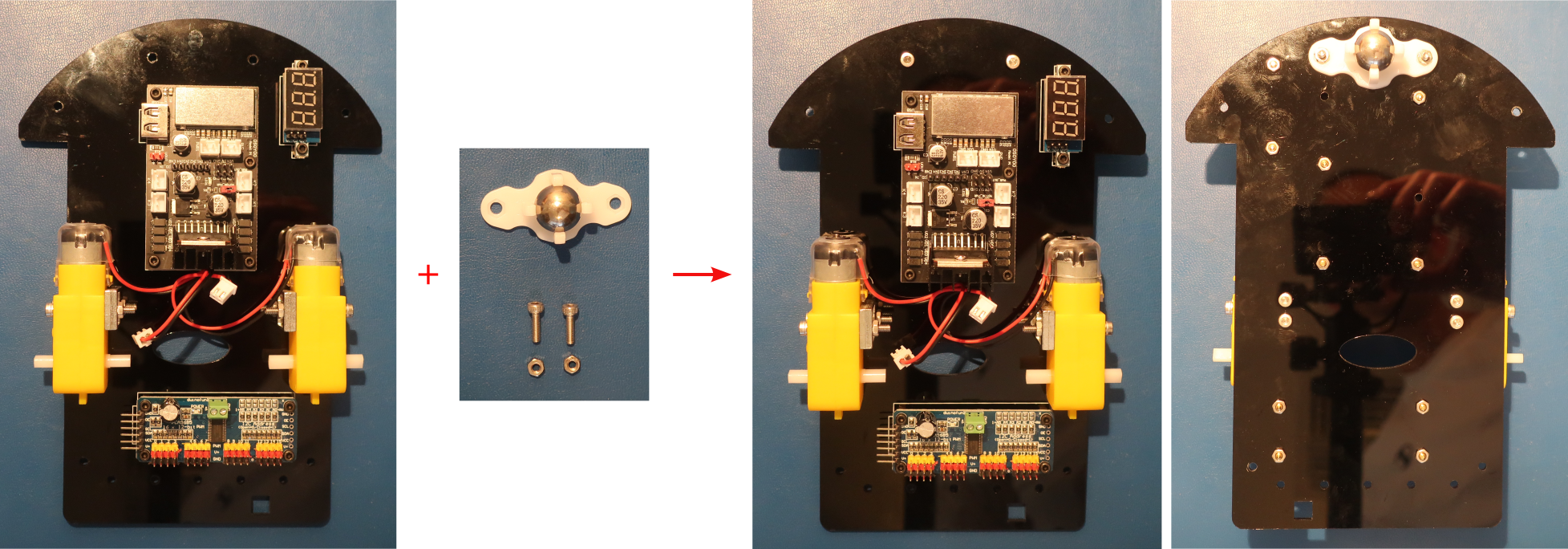
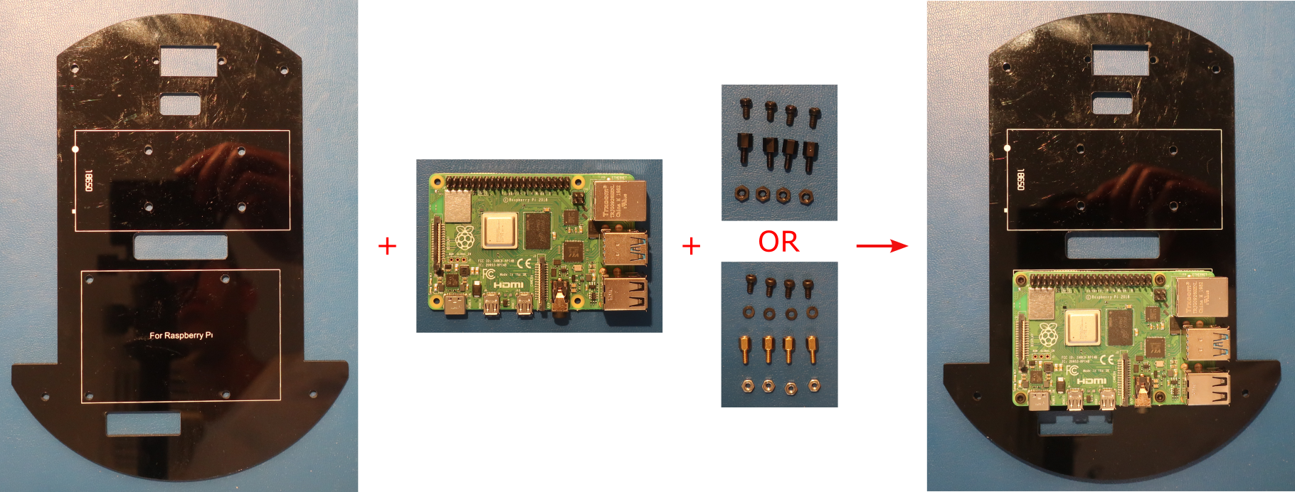
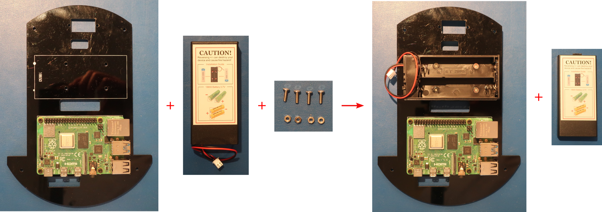
- Install the OSOYOO Model Pi motor driver module on bottom car chassis with with 4pcs M2.5x5mm screws, M2.5x5mm+6mm pillars, and M2.5 nuts from the hardware kit as shown below
Make sure the OSOYOO Model Pi motor driver module is installed in the correct direction as shown on the right below
If using brass pillars insert an M2.5 plastic washer between the Model Pi motor driver module and each pillar
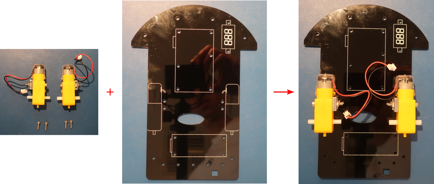
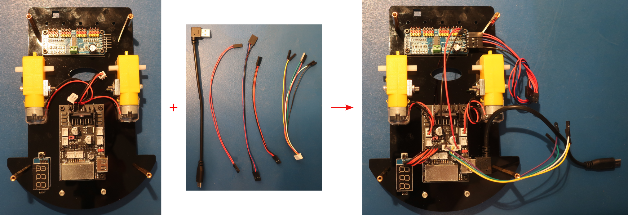
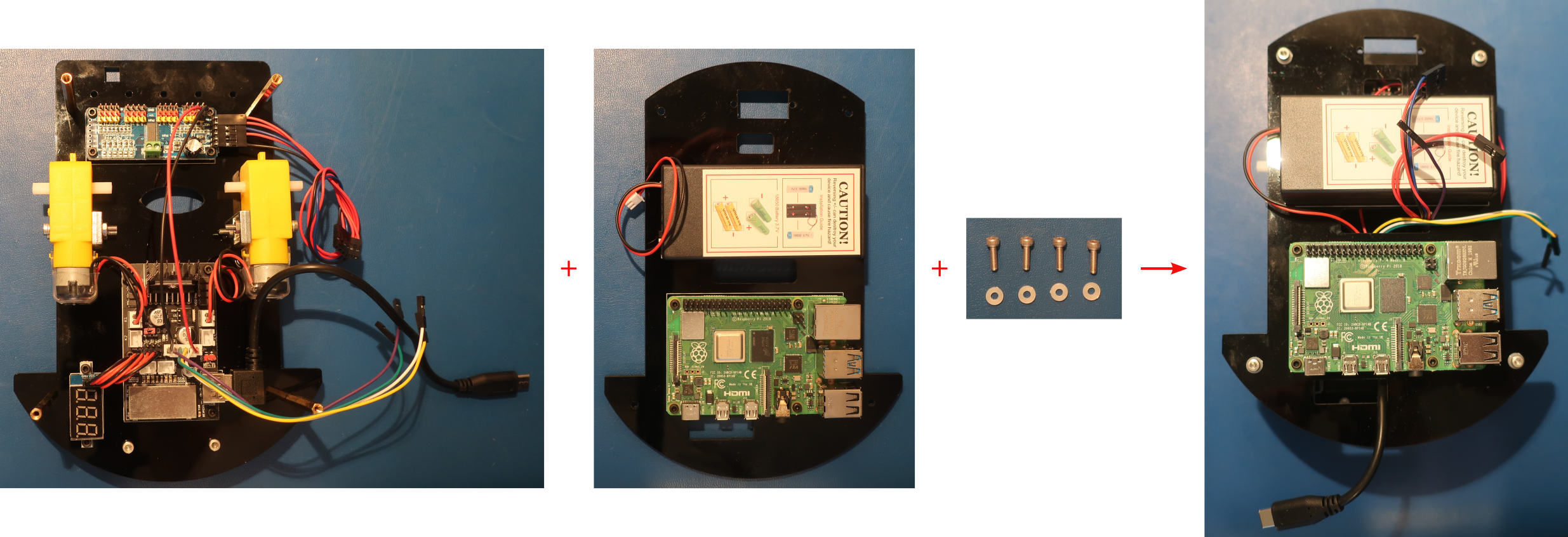
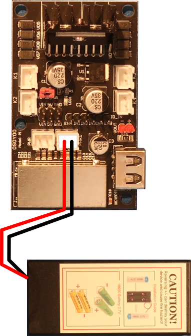
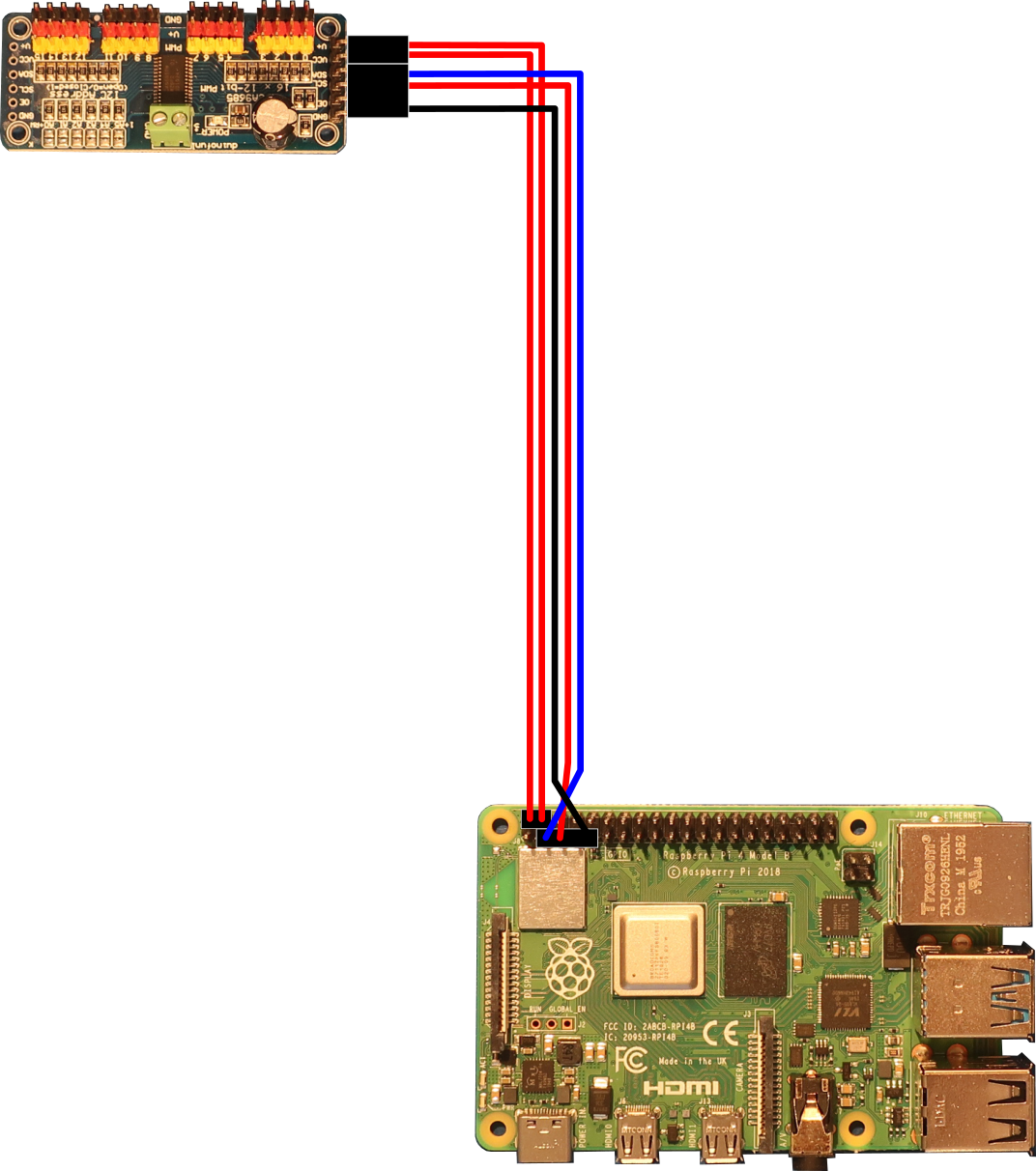
- Connect the wires between the boards on the bottom chassis as described below
- Connect the 2pin 20cm and 3pin 20cm female to female cables to the PCA9685 compatible board as shown below
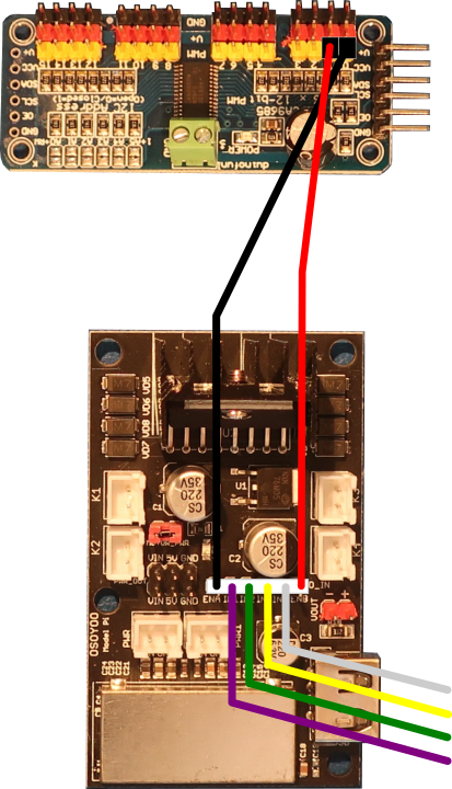
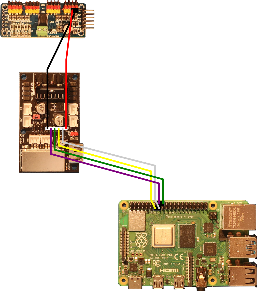
- Connect the 6pin flying lead cable between the Model Pi motor driver board and the PCA9685 compatible board as shown below
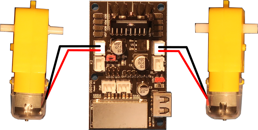
- Connect the motors to the Model Pi motor driver board as shown below
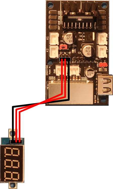
- Connect the 3pin 15cm female to female between the voltage meter and the Model Pi motor driver board as shown below
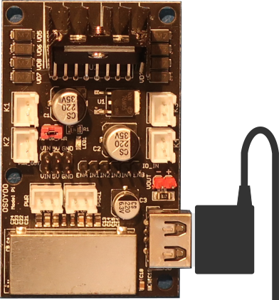
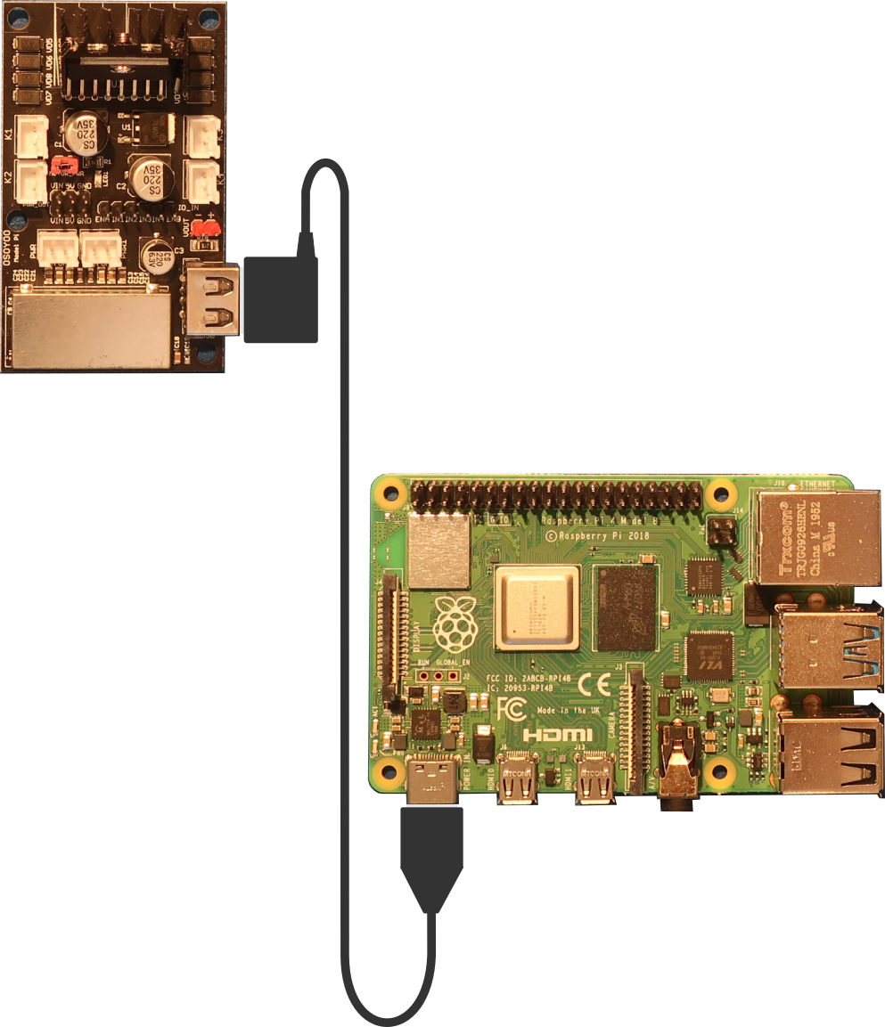
- Connect the USB cable to the Model Pi motor driver board as shown below
Create loops in the wires by wrapping them around your finger to keep the wiring neat
Use the USB-A to USB-C cable for the Raspberry Pi 4. Use the USB-A to USB-micro B cable for the Raspberry Pi 3B.
Model Pi Motor Driver Board PCA9685 Module Raspberry Pi Board ENA PWM 0 — IN1 — Pin 16 (GPIO 23) IN2 — Pin 18 (GPIO 24) IN3 — Pin 13 (GPIO 27) IN4 — Pin 15 (GPIO 22) ENB PWM 1 — Model Pi Motor Driver Board Voltage Meter VIN VT 5V VCC GND GND
Software
Select the appropriate link below for instructions to setup the software on the PiBot and an exploration of how it works.
Electrical Description
The OSOYOO Model Pi motor driver board is the heart of the PiBot. It is an improved L298N module which can power the motors and the Raspberry Pi at the same time. This board supports all the features of the L298N DC motor drive and also has a USB 5V output port which provides a stable voltage to the Raspberry Pi board up to 2.4A. It is fully compatible with the L298N control input signals ENA, IN1, IN2, IN3, IN4, and ENB. Each channel has two output sockets, K1 and K2 for the right side motors and K3 and K4 for the left side motors. The input power source can be any voltage between 7.5V and 24V. Recommended battery configurations are 2pcs tandem 18650 batteries, 6pcs tandem AA batteries, or 2pcs parallel 9V batteries.
The ENA input to the Model Pi board gets a PWM signal from the PCA9685 compatible board which is controlled by the Raspberry Pi. This creates an analog current through the motor using the L298N H-bridge. The higher the PWM value from the Raspberry Pi, the more current will go through the motor, and the faster the motor will spin. The ENA input controls the K1 and K2 outputs which are connected to the right side motors.
The ENB input to the Model Pi board gets a separate PWM signal from the PCA9685 compatible board. This creates an analog current through the motor using the L298N H-bridge in the same way that the ENA input works. The ENB input controls the K3 and K4 outputs which are connected to the left side motors.
The IN1 and IN2 inputs to the Model Pi board get digital signals from the Raspberry Pi. These inputs control the L298N H-bridge to determine the direction that the motor rotates. When IN1=HIGH(1) and IN2=LOW(0) the motor moves forward. When IN1=LOW(0) and IN2=HIGH(1) the motor moves backward. The IN1 and IN2 inputs control the K1 and K2 outputs which are connected to the right side motors
The IN3 and IN4 inputs to the Model Pi board get separate digital signals from the Raspberry Pi. These inputs control the L298N H-bridge to determine the direction that the motor rotates in the same way that the IN1 and IN2 inputs work. The IN3 and IN4 inputs control the K3 and K4 outputs which are connected to the left side motors
The PCA9685 compatible board connects to the Raspberry Pi I2C bus. The Raspberry Pi can send commands to the PCA9685 compatible board to create the PWM signals used for the ENA and ENB signals to the Model Pi board. The PCA9685 compatible board has 16 PWM outputs, but the PiBot only use two of them, PWM0 and PWM1.
The Raspberry Pi is the brains of the PiBot. It runs the Python programs which send the commands to the Model Pi board in order to make the PiBot do what you want it to do. It also can receive status from sensors that tell it where it is and allow it to make decisions about what to do without you. This capability will be explored in the following lessons.


